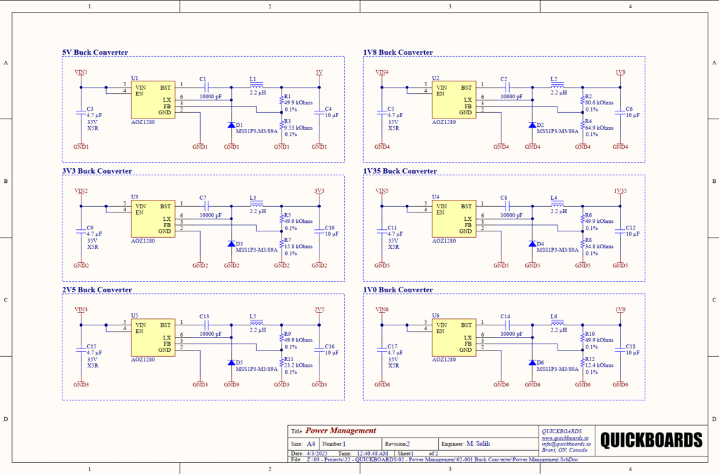
AOZ1280 5V/3V3/2V5/1V8/1V35/1V Buck Converter Reference Schematic Design
The AOZ1280 is a high-efficiency, simple-to-use asynchronous step-down regulator capable of delivering up to 1.2A of continuous output current. Part of the EZBuck family, this integrated circuit is designed to minimize external component count while providing a wide input voltage range, making it a versatile choice for point-of-load (POL) regulation. It is typically found in applications such as set-top boxes, industrial power systems, and consumer electronics where board space is at a premium and high switching frequencies are required to reduce the size of the power inductor.
Unlock the Quickboards Library
Get instant access to this Altium Schematic and hundreds of other subcircuits. Hardware design, modularized. Schematic + Layout + Firmware. Built to IPC standards for zero re-spins.
Overview of the AOZ1280
The device operates from an input voltage range of 3V to 26V and utilizes a fixed 1.5MHz switching frequency. This high frequency allows for the use of small surface-mount inductors and capacitors, which is critical for modular designs. The internal power MOSFET and simplified control loop ensure high efficiency across various load conditions, while integrated protection features like over-current and thermal shutdown provide a robust foundation for reliable power delivery.
| Feature | Specification |
| Input Voltage Range | 3V to 26V |
| Output Current | 1.2A Maximum |
| Switching Frequency | 1.5MHz |
| Feedback Voltage | 0.8V |
| Duty Cycle | Up to 100% |
| Package | SOT23-6 |
| Protection | Thermal and Over-current |
Pin Configuration and Function Mapping
The AOZ1280 is housed in a compact SOT23-6 package, optimized for thermal performance and ease of routing in dense PCB layouts.
| Pin Number | Primary Function | Secondary / Peripheral Functions |
| 1 | BST | Bootstrap for High-Side Driver |
| 2 | GND | Power Ground Reference |
| 3 | FB | Feedback Input for Output Regulation |
| 4 | EN | Enable Input (High = On) |
| 5 | VIN | Supply Input Voltage |
| 6 | LX | Switching Node Connection |
Functional Block Analysis & Design Decisions
Power Conversion and Switching Node
The switching sub-circuit is the core of the AOZ1280 design, consisting of the LX pin (Pin 6), a 2.2uH power inductor (L1-L6), and a Schottky freewheeling diode (D1-D6). The inductor value of 2.2uH was selected as a balanced choice for the 1.5MHz switching frequency, providing a reasonable ripple current while ensuring fast transient response. The Schottky diode, specifically the MSS1P3-M3/89A, is selected for its low forward voltage and fast recovery time, which significantly reduces switching losses compared to standard silicon diodes. Ceramic capacitors (C4, C6, etc.) of 10uF provide the primary output filtering, smoothing the inductor current into a stable DC voltage.
Input Decoupling and Bootstrap Circuit
For high-frequency switching regulators, input decoupling is paramount to prevent switching noise from propagating back to the supply rail. The schematic utilizes a 4.7uF ceramic capacitor (C3, C5, C9, etc.) rated for 35V with an X5R dielectric. The 35V rating provides ample headroom for transient spikes, while the X5R material ensures capacitance remains relatively stable over temperature. Pin 1 (BST) is connected to a 10000pF (10nF) ceramic capacitor (C1, C2, etc.) tied to the LX node. This bootstrap circuit is necessary to provide the gate-drive voltage for the internal high-side N-channel MOSFET, allowing it to turn on fully even when the source voltage is equal to the input voltage.
Feedback Network and Voltage Setting
The output voltage is determined by a high-precision resistor divider connected to the FB pin. In this multi-output reference design, the top resistor (R1, R2, R5, etc.) is standardized at 49.9kOhms with a 0.1% tolerance. Using 0.1% tolerance resistors is a senior-level design choice to minimize output voltage error and drift over time. The bottom resistor (R3, R4, R7, etc.) is varied to set the desired output voltage based on the internal 0.8V reference. For example, a 9.53kOhm resistor is used for a 5V output, while a 12.4kOhm resistor is used for 1V0. This high-impedance network is susceptible to noise, necessitating careful placement away from the switching LX node.
Implementation Insights
When integrating the AOZ1280 block, the physical layout must prioritize the high di/dt loops. The input capacitor (4.7uF) must be placed as close as possible to the VIN and GND pins of the IC to minimize parasitic inductance, which can lead to voltage ringing and EMI issues. Similarly, the Schottky diode and the LX switching node should be kept small to reduce radiated noise. A solid ground plane is essential for both thermal dissipation and as a return path for switching currents; the thermal resistance of the SOT23-6 package relies heavily on the PCB copper area connected to the GND pin.
Care must be given to the minimum load requirements and stability. If using ultra-low ESR ceramic capacitors for the output, ensure that the control loop remains stable across the full operating range. Additionally, while the AOZ1280 supports up to a 100% duty cycle, the bootstrap capacitor must have sufficient time to recharge; in very high duty cycle applications nearing dropout, the high-side driver supply may drop below the required threshold if the switching node does not stay low long enough.
Applications
- Point of Load (POL) Converters: Providing stable secondary rails for FPGAs, ASICs, and microprocessors in complex digital systems.
- Industrial Power Supplies: Converting 12V or 24V bus voltages down to 5V or 3.3V logic levels with high reliability.
- Set-Top Boxes and Networking: Efficiently managing power in space-constrained consumer electronics.
- Automotive Infotainment: Regulating power for display and communication modules where a wide input voltage range is necessary.
Integrating the AOZ1280 into your design
This modular block provides a validated, multi-rail power solution that eliminates the need for manual calculation of feedback networks and inductor sizing. By providing pre-configured configurations for 5V, 3V3, 2V5, 1V8, 1V35, and 1V0 rails, this schematic set allows engineers to drop high-efficiency power stages directly into their projects. The standardized 0.1% resistor values ensure that the power tree meets the stringent accuracy requirements of modern high-speed digital logic.
Skip the tedious research and manual entry. Download the production-ready schematic block for the AOZ1280 directly from the Quickboards Library.