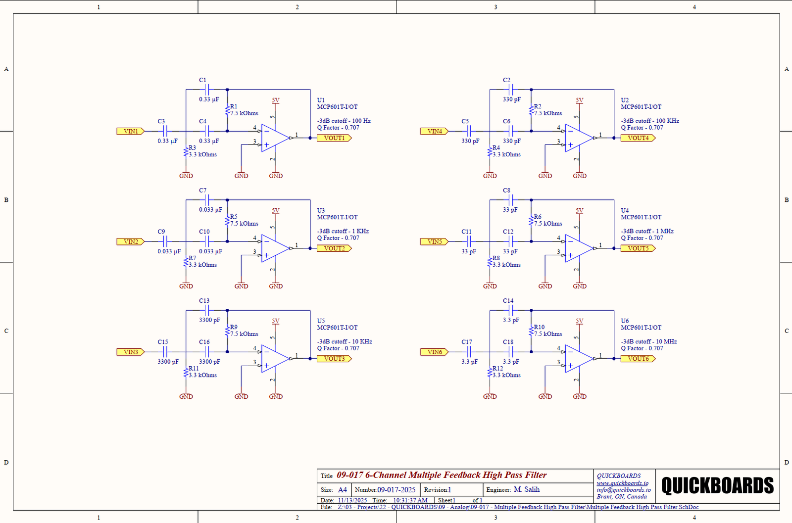
Multiple-Feedback Band-Pass Filter Calculator
This is a second-order, active multiple feedback band pass filter calculator. Set the desired cutoff frequency and Q factor to generate resistor and capacitor values, then adjust the bode plot max frequency to view the response over the desired frequency sweep.

Filter Requirements
Component Results
Bode Plot Analysis
Build this circuit
Bridge the gap by downloading the validated Multiple Feedback High Pass Filter Block from the Quickboards Library. Eliminate R&D uncertainty and slash design time by assembling subcircuit schematics from a library of Processors, Sensors, Power Management, ADC/DACs, Memory, Interface circuits and more. Download the full library here.