POM-3535L-3-R Electret Condenser Microphone Reference Schematic Design
The POM-3535L-3-R is a high-sensitivity, omnidirectional electret condenser microphone (ECM) designed for high-fidelity audio capture in compact electronic systems. Its primary function is to convert acoustic pressure waves into a proportional analog electrical signal. This component is typically utilized in voice-activated IoT devices, wearable technology, and smart home appliances where space-constrained audio sensing is required. Its omnidirectional pickup pattern ensures consistent performance regardless of the device’s orientation relative to the sound source.
Overview of the POM-3535L-3-R
The POM-3535L-3-R utilizes a permanently polarized electret capsule and an internal JFET (Junction Field Effect Transistor) to provide high impedance conversion. This architecture allows the microphone to drive a signal over standard PCB traces without significant signal degradation. The sensor is engineered for a flat frequency response across the audible spectrum, making it a versatile choice for both simple sound detection and complex voice recognition tasks.
| Technical Specification | Details |
| Operating Voltage Range | 1.5V to 10V |
| Sensitivity | -35 +/- 3 dB (at 1 kHz) |
| Frequency Range | 50 Hz to 12,000 Hz |
| Max Current Consumption | 0.5 mA |
| Signal-to-Noise Ratio | 60 dB |
| Output Impedance | 2.2 kOhms |
| Directional Characteristic | Omnidirectional |
| Dimensions | 3.5 mm Diameter x 3.5 mm Height |
Pin Configuration and Function Mapping
The POM-3535L-3-R utilizes a simplified two-terminal interface, integrating the bias and output signal into a single node to minimize footprint.
| Pin Number | Primary Function | Secondary / Peripheral Functions |
| 1 | Output / Bias | Audio Signal Output and DC Biasing Node |
| 2 | Ground | Common Reference / Shield Connection |
Functional Block Analysis & Design Decisions
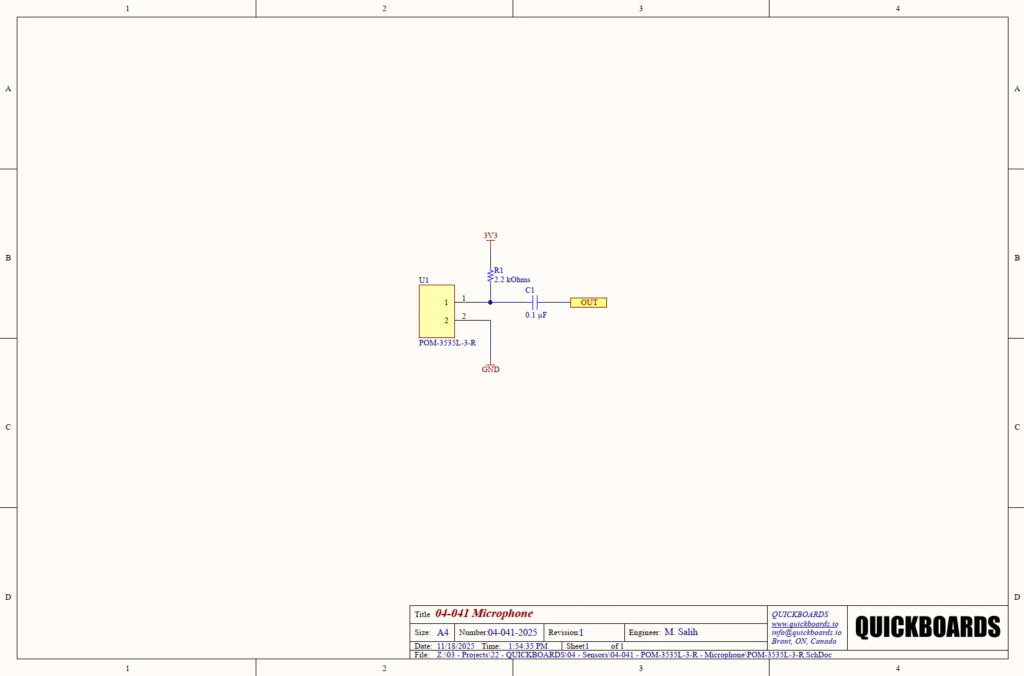
Biasing and Signal Conditioning Block
The schematic implements a standard common-source JFET biasing configuration. Because the electret capsule is a passive capacitive element, the internal JFET requires a DC bias to function as an impedance converter. R1 (2.2 kOhms) serves as the load resistor, pulling Pin 1 up to the 3.3V (3V3) rail. This value is selected to match the internal impedance of the microphone, ensuring maximum power transfer and optimizing the gain of the internal FET stage. Junior engineers should note that the bias resistor determines the operating current; a value too high will starve the FET, while a value too low will increase power consumption and potentially introduce distortion.
AC Coupling and DC Blocking
C1 (0.1 microfarad) is the AC coupling capacitor. Its primary role is to block the DC bias voltage on Pin 1 from reaching the input of the downstream amplifier or Analog-to-Digital Converter (ADC), while allowing the AC audio signal to pass through. The choice of 0.1 microfarad is standard for general-purpose audio sensing, though senior engineers will recognize that this capacitor forms a high-pass filter in conjunction with the input impedance of the following stage. Ceramic X7R capacitors are recommended here for their stability across temperature variations and low leakage current, which is paramount in high-impedance audio paths to prevent “pop” noises or DC offset shifts.
Placement & Trace Logic
The audio signal path between the microphone and the coupling capacitor is highly susceptible to electromagnetic interference (EMI). Physical layout requires the microphone to be placed as close to the pre-amplifier or ADC as possible. The ground connection on Pin 2 must be tied to a solid, quiet ground plane. For senior engineers, it is critical to ensure that no high-speed digital traces—such as I2C or PWM lines—run parallel to the OUT net, as the high impedance of the ECM signal path makes it an efficient antenna for digital crosstalk.
Design Rationale
The decision to utilize a 3.3V supply and a 2.2 kOhm bias resistor aligns the modular block with modern low-power microcontroller logic levels. This configuration ensures that the microphone operates within its linear region, providing a clean analog output that can be directly fed into a high-gain differential amplifier or a codec’s programmable gain amplifier (PGA).
Implementation Insights
A primary engineering consideration is the acoustic pathing within the final product enclosure. The performance of the POM-3535L-3-R is heavily dependent on the mechanical seal between the microphone face and the device housing. Any air leakage around the microphone will result in a significant loss of low-frequency response and may introduce unwanted resonance peaks.
Maintaining a clean power supply is essential for audio sensing. ECMs have a very low Power Supply Rejection Ratio (PSRR), meaning any ripple or noise on the 3V3 rail will be amplified and appear in the audio signal as a hum or hiss. In high-performance applications, it is advisable to use a dedicated low-dropout (LDO) regulator or an RC filter for the microphone’s bias supply to isolate it from noisy digital rails.
The soldering process requires careful thermal management. Excess heat applied to the microphone terminals can damage the delicate electret membrane or the internal JFET. It is recommended to use hand soldering with controlled temperatures or a specific reflow profile tailored for MEMS and ECM components to ensure long-term reliability.
Applications
- Voice-Activated Interfaces: Providing a reliable audio input for smart assistants and voice-controlled appliances.
- IoT Environmental Monitoring: Detecting sound levels in industrial or residential areas for noise pollution tracking.
- Wearable Technology: Integrating discrete audio capture into fitness trackers and smart eyewear.
- Security Systems: Serving as a primary sensor for glass-break detectors or acoustic intrusion alarms.
integrating the POM-3535L-3-R into your design
The POM-3535L-3-R 04-041 microphone modular block provides a production-ready solution for high-fidelity audio sensing. By utilizing a pre-validated biasing and AC coupling architecture, this design eliminates the uncertainty associated with JFET impedance matching and signal conditioning. This building block ensures that the sensitive analog audio core is correctly supported, allowing design teams to focus on digital signal processing and acoustic housing while reducing the risk of noise-related PCB re-spins.
Skip the tedious research and manual entry. Download the production-ready schematic block for the POM-3535L-3-R directly from the Quickboards Library.