MCP601T-I/OT 8 Channel Active High Pass Filter Reference Schematic Design
The MCP601T-I/OT is a single, rail-to-rail output operational amplifier designed for low-power, high-performance applications. In this modular subcircuit, it is utilized as an active buffer for an 8-channel high-pass filter array. By combining a passive RC high-pass network with an active unity-gain buffer, this design provides high-reliability frequency discrimination without the signal degradation typically associated with loading effects in passive-only circuits. It is commonly found in battery-powered instrumentation, sensor signal conditioning, and audio processing stages where removing DC offsets or low-frequency noise is paramount.
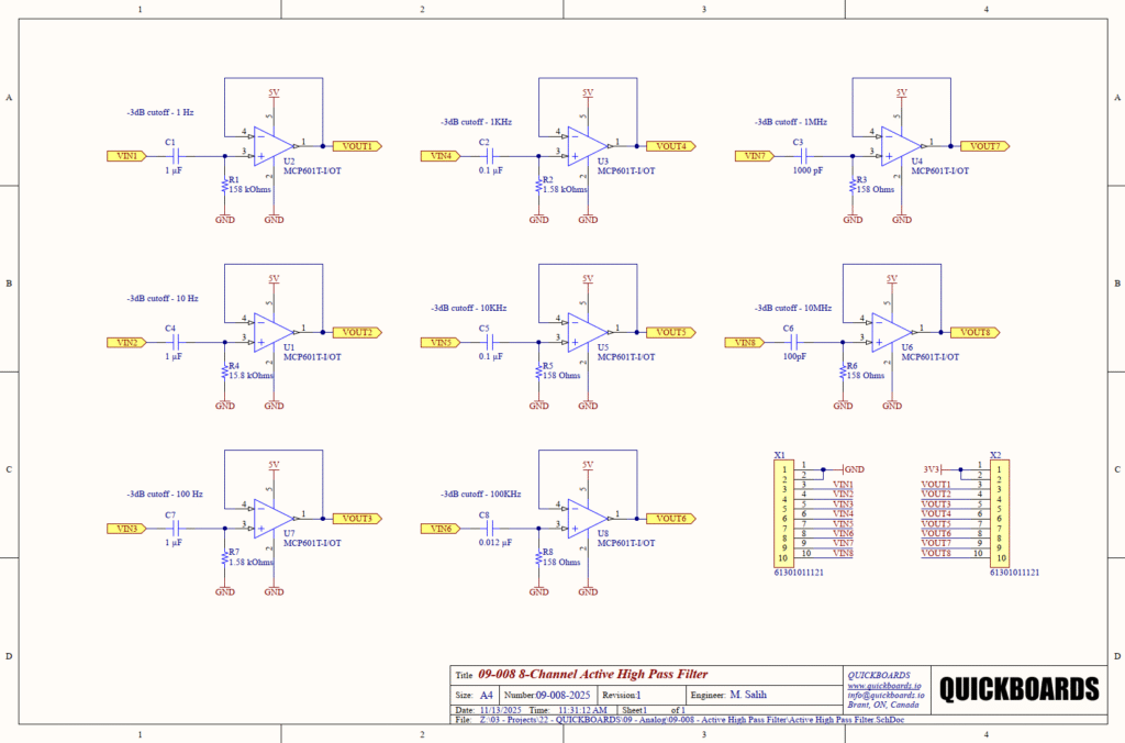
Overview of the Active High Pass Filter
The MCP601 belongs to a family of CMOS op-amps that offer a Gain Bandwidth Product (GBWP) of 2.8 MHz and a low typical operating current of only 230 microamps. Its rail-to-rail output swing allows for maximum dynamic range even when operating from a single 2.7V to 6V supply. This specific 8-channel block uses the IC to isolate sensitive filter poles, ensuring that the -3dB cutoff frequency remains stable regardless of the input impedance of the downstream stage (e.g., an Analog-to-Digital Converter or a secondary gain stage).
| Feature | Specification |
| Supply Voltage | 2.7V to 6.0V |
| Gain Bandwidth Product | 2.8 MHz |
| Slew Rate | 2.3 V/microsecond |
| Typical Quiescent Current | 230 microamps |
| Input Offset Voltage | 2 mV (Maximum) |
| Output Drive | Rail-to-Rail |
| Package Type | 5-Lead SOT-23 |
Pin Configuration and Function Mapping
The MCP601T-I/OT is housed in a compact SOT-23-5 package, optimizing board real estate for multi-channel high-density designs.
| Pin Number | Primary Function | Secondary / Peripheral Functions |
| 1 | VOUT | Amplifier Output Signal |
| 2 | VSS | Negative Power Supply / Ground |
| 3 | VIN+ | Non-Inverting Input (Signal Input) |
| 4 | VIN- | Inverting Input (Feedback Connection) |
| 5 | VDD | Positive Power Supply (5V) |
Functional Block Analysis & Design Decisions
Passive High-Pass Filter Stage
Each of the eight channels begins with a passive RC high-pass sub-circuit consisting of a series capacitor (C1 through C8) and a shunt resistor to ground (R1 through R8). This topology is chosen for its simplicity and inherent DC-blocking capability. In a high-pass configuration, the capacitor blocks low-frequency and DC components while allowing high-frequency signals to pass to the op-amp. The resistor provides a critical return path to ground for the op-amp’s input bias current, preventing the non-inverting input from floating to a rail—a standard requirement for CMOS amplifiers.
Active Unity-Gain Buffer
The MCP601 is configured in a voltage follower (unity-gain) mode by tying the inverting input (Pin 4) directly to the output (Pin 1). This functional block provides near-infinite input impedance to the passive filter stage, ensuring that the calculated -3dB cutoff frequency remains accurate. Without this active stage, connecting the filter to a low-impedance load would significantly shift the filter pole and attenuate the passband signal. The low output impedance of the MCP601 ensures it can drive relatively long PCB traces or downstream capacitive loads with minimal phase shift.
Component Selection
Resistor values (e.g., 158 kOhms, 15.8 kOhms, 158 Ohms) are selected from the E96 1% tolerance series to achieve precise decade-based cutoff frequencies. Capacitors for low-frequency channels (1 Hz to 100 Hz) utilize 1 microfarad ceramic types. For high-frequency channels (1 MHz and 10 MHz), the capacitance is scaled down to 1000 pF and 100 pF. In these high-frequency stages, Ceramic C0G/NP0 dielectrics are mandatory because of their superior stability and low voltage coefficient, ensuring the filter does not drift with signal amplitude. Lower frequency channels typically utilize X7R dielectrics for their balance of size and performance.
Placement & Trace Logic
To maintain signal integrity, the series capacitor must be placed as close as possible to the non-inverting input (Pin 3). This minimizes the trace area of the high-impedance node, reducing susceptibility to electromagnetic interference (EMI). The ground connection for the shunt resistor should be made directly to a solid ground plane to prevent ground-loop noise from modulating the filter baseline.
Implementation Insights
A primary engineering consideration for this block is the Gain Bandwidth Product (GBWP). While the MCP601 supports frequencies up to 2.8 MHz, the 10 MHz channel (Channel 8) in this design is intended to operate at the edge of the amplifier’s performance envelope. At these frequencies, the op-amp functions primarily as a limiter; senior engineers should ensure that the signal amplitude does not exceed the slew-rate limits of the device (2.3 V/microsecond) to avoid non-linear distortion.
Another consideration is the supply decoupling. Although not shown in the individual channel breakdowns, a 0.1 microfarad ceramic decoupling capacitor must be placed within 2 mm of Pin 5 (VDD) for every IC in the 8-channel array. High-speed switching noise on the power rail can couple into the high-impedance input pins, manifesting as audible noise or conversion errors.
Grounding for mixed-signal systems is critical. Since this block often interfaces with high-speed ADCs, it is recommended to keep the analog return paths separate from high-current digital return paths until they reach a single “star ground” point to minimize ground bounce.
Applications
- Audio Signal Processing: Removing sub-sonic “rumble” or DC offsets from microphone and line-level signals.
- Sensor Baseline Restoration: Stabilizing the AC signal from piezo sensors or photodiodes by removing slow-moving ambient light or mechanical drift.
- Medical Instrumentation: Removing the large DC offsets found in biopotential electrodes (ECG/EEG) while preserving high-frequency signal data.
- Portable Data Acquisition: Functioning as a high-impedance input stage for handheld loggers that require zero loading on sensitive sensors.
Integrating the MCP601T-I/OT into your design
This 8-channel active high-pass filter block provides a production-ready solution for managing DC offsets and baseline stability across seven decades of frequency. By providing pre-validated RC values and an active buffer stage, this modular block eliminates the tedious iterative calculations and loading-effect simulations required in traditional analog design. It ensures a stable, low-impedance output that is ready to interface with any modern digital system.
Skip the tedious research and manual entry. Download the production-ready schematic block for the MCP601T-I/OT directly from the Quickboards Library.