LTR-390UV-01 UV and Ambient Light Sensor Reference Schematic Design
The LTR-390UV-01 is a high-accuracy, low-voltage digital light sensor that integrates both an ambient light sensor (ALS) and an ultraviolet light sensor (UVS) into a single miniature chip-scale package. Its primary function is to convert light intensity into a digital signal output capable of measuring the UV index and illuminance levels in the surrounding environment. This integrated circuit is widely utilized in wearable devices for sunlight exposure monitoring, smartphones for display brightness control, and outdoor IoT weather stations. By leveraging a specialized photodiode spectral response, the sensor can accurately distinguish between visible light and harmful UV radiation.
Overview of the LTR-390UV-01
The LTR-390UV-01 operates over a standard I2C interface and provides up to 20-bit resolution for both UVS and ALS modes. This high dynamic range allows the sensor to operate effectively in environments ranging from low-light indoor settings to direct, high-intensity sunlight. The device features an ultra-low power consumption profile, making it suitable for battery-operated platforms where energy efficiency is a primary design requirement.
| Technical Specification | Details |
| Supply Voltage (VDD) | 1.7V to 3.6V |
| Interface | I2C (up to 400 kHz) |
| Resolution | 13 to 20-bit (Programmable) |
| ALS Spectral Response | Closely matches human eye |
| UV Spectral Response | 280 nm to 430 nm |
| Current Consumption | 0.5 uA (Standby), 110 uA (Active) |
| Operating Temperature | -40 to 85 Celsius |
| Package Type | 6-pin ChipLED |
Pin Configuration and Function Mapping
The LTR-390UV-01 utilizes a 6-pin footprint that separates the analog power requirements from the digital communication bus.
| Pin Number | Primary Function | Secondary / Peripheral Functions |
| 1 | VDD | Positive Power Supply Input |
| 2 | NC | No Internal Connection |
| 3 | GND | Ground Reference |
| 4 | SCL | I2C Serial Clock Input |
| 5 | INT | Programmable Interrupt Output |
| 6 | SDA | I2C Serial Data Input/Output |
Functional Block Analysis & Design Decisions
Power and Decoupling Block
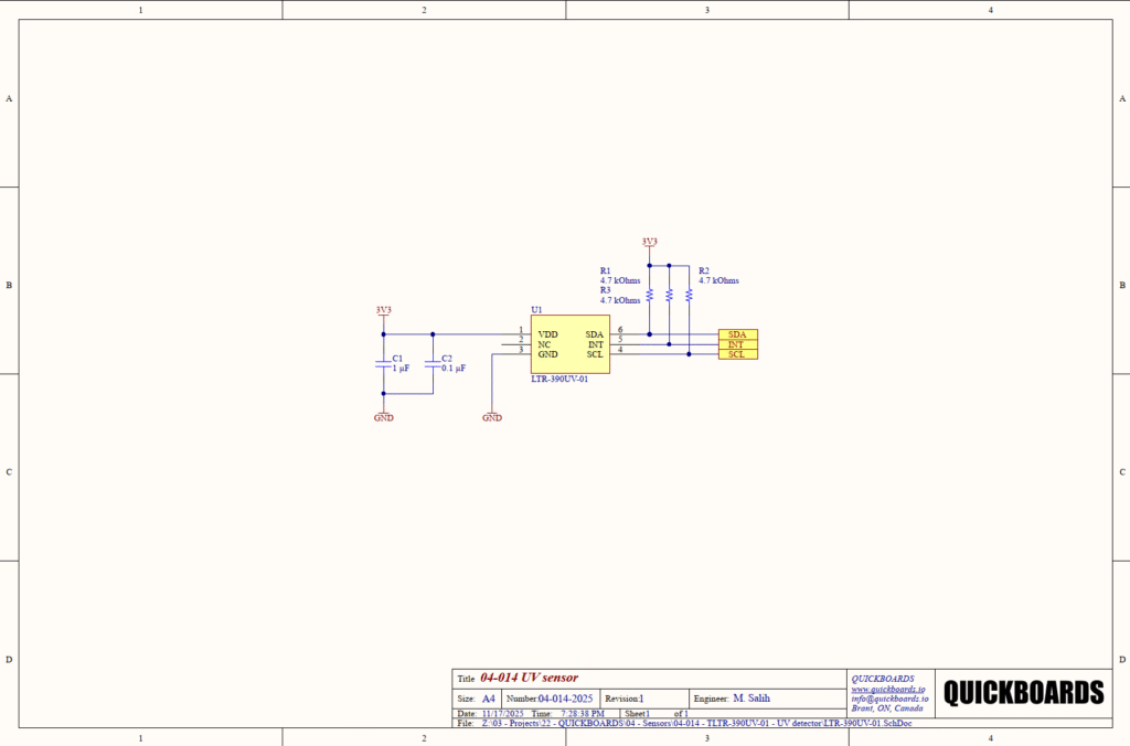
The VDD supply (Pin 1) is supported by a dual-capacitor decoupling network consisting of C1 (1 uF) and C2 (0.1 uF). Mixed-signal sensors like the LTR-390 are susceptible to high-frequency noise on the power rail, which can introduce jitter or measurement offsets into the sensitive internal ADC stages. The 0.1 uF ceramic capacitor is selected for its low equivalent series inductance (ESL) to filter out fast switching transients from the I2C bus and nearby digital logic. The 1 uF capacitor provides localized bulk storage to maintain supply stability during the sensor’s integration cycles. Ceramic X7R capacitors are specified here for their superior temperature stability and lower voltage derating compared to standard electrolytic or Y5V alternatives.
I2C Communication and Interrupt Interface
The digital interface block includes the I2C bus (SDA/SCL) and a dedicated hardware interrupt (INT). This reference design utilizes three 4.7 kOhm pull-up resistors (R1, R2, R3) tied to the 3.3V (3V3) rail. The choice of 4.7 kOhms is a senior-level design standard for 400 kHz Fast-mode I2C; it provides a sufficiently fast rise time to meet timing specifications while minimizing static power consumption when the bus is pulled low. The INT pin is an open-drain output, allowing the sensor to trigger a host wake-up based on user-defined light thresholds. This is a critical design choice for low-power systems, as it eliminates the need for the host MCU to constantly poll the sensor for data.
Placement & Trace Logic
The physical layout of the LTR-390UV-01 is governed by optical and electrical requirements. The decoupling capacitors C1 and C2 must be placed within 2 mm of Pin 1 to ensure effective filtering. Electrically, the digital traces for SDA and SCL should be routed away from sensitive analog signals to prevent crosstalk. Mechanically, the sensor must be placed under a UV-transparent window (such as fused silica or specific UV-rated plastics) to avoid attenuating the UV spectrum. Senior engineers should ensure that the distance between the sensor and the enclosure window is minimized to reduce internal reflections and increase the effective field of view.
Design Rationale
The decision to utilize a 3.3V rail and 4.7 kOhm pull-ups ensures broad compatibility with standard 3.3V logic levels found in most modern microcontrollers. Tying Pin 2 to a floating state or an isolated pad is required, as it has no internal electrical connection and should not be used for signal routing.
Implementation Insights
A primary engineering consideration for the LTR-390UV-01 is the spectral transmission of the device enclosure. Standard glass and many common plastics effectively block UV radiation. If the sensor is placed behind a standard window, the UV index readings will be significantly lower than reality. Engineers must select a material with high transmission between 280 nm and 430 nm or implement a calibration factor in the host firmware to compensate for the material’s attenuation.
Another consideration involves the I2C bus capacitance. If the LTR-390 is placed on a long cable or a large PCB with multiple I2C devices, the total bus capacitance may exceed the 400 pF limit for Fast-mode. In such cases, the pull-up resistor values may need to be reduced (e.g., to 2.2 kOhms) to maintain signal integrity, though this will increase current consumption during communication.
Finally, manage the “dark current” and light leakage. In high-precision applications, the sensor should be optically isolated from internal light sources within the device (such as LED indicators or display backlights). Light leakage through the PCB or enclosure can lead to significant offsets in the ALS and UVS readings, especially in low-light environments.
Applications
- Wearable Health Monitors: Tracking daily UV exposure and providing user alerts to prevent overexposure to sunlight.
- Smartphones and Tablets: Adjusting display brightness and white balance based on ambient lighting conditions to improve battery life and user comfort.
- Outdoor Weather Stations: Measuring the UV index as part of a comprehensive environmental monitoring suite.
- Industrial Light Monitoring: Ensuring UV levels in specialized manufacturing processes (such as UV curing) remain within specified tolerances.
- Smart Home Automation: Controlling automated blinds or outdoor lighting systems based on real-time solar intensity data.
Integrating the LTR-390UV-01 into your design
The LTR-390UV-01 04-014 UV sensor modular block provides a validated, production-ready solution for high-precision light and UV sensing. By utilizing the pre-tested decoupling and pull-up architecture, engineers can bypass the complexities of I2C bus tuning and supply stability research. This reusable building block ensures that the sensitive 20-bit optical core is correctly supported, allowing design teams to focus on the spectral calibration and mechanical housing design required for their specific application.
Skip the tedious research and manual entry. Download the production-ready schematic block for the LTR-390UV-01 directly from the Quickboards Library.