LTR-329ALS-01 Light Intensity Sensor Reference Schematic Design
The LTR-329ALS-01 is a low-voltage, digital ambient light sensor (ALS) that converts light intensity into a digital output signal capable of being read over an I2C interface. It is specifically designed to provide a spectral response that closely mimics the human eye’s perception of light, allowing for accurate illuminance measurements in diverse lighting environments. This integrated circuit is a fundamental building block in consumer electronics and industrial systems for functions like automated backlight dimming, display brightness control, and daylight harvesting.
Common applications include smartphones and tablets for adaptive screen brightness, notebooks and monitors for power management, and smart home IoT nodes for environmental light monitoring and automated lighting control.
| Technical Specification | Value |
| Supply Voltage (VDD) | 2.4V to 3.6V |
| I2C Interface Frequency | Up to 400 kHz (Fast Mode) |
| Digital Resolution | 16-bit |
| Operating Current | 110 microamps (Active typical) |
| Standby Current | 5 microamps (Typical) |
| Dynamic Range | 0.01 to 64,000 lux |
| Spectral Response | Matches human eye (Photopic) |
| Package Type | 4-pin ChipLED |
Pin Configuration and Function Mapping
The LTR-329ALS-01 is housed in a compact footprint that optimizes board real estate while maintaining a reliable digital connection.
| Pin Number | Primary Function | Secondary / Peripheral Functions |
| 1 | VDD | Power Supply Input (3.3V) |
| 2 | GND | System Ground |
| 3 | SDA | I2C Serial Data (Digital I/O) |
| 4 | SCL | I2C Serial Clock (Digital Input) |
Functional Block Analysis & Design Decisions
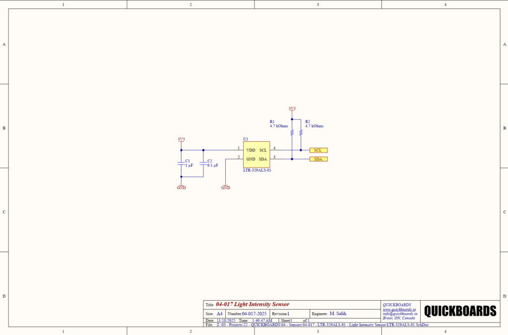
Power and Decoupling Block
The supply node (VDD) at Pin 1 is supported by a parallel decoupling capacitor network consisting of C1 (1 microfarad) and C2 (0.1 microfarad). High-precision optical sensors like the LTR-329ALS-01 are sensitive to power supply ripples, which can manifest as jitter or measurement offsets in the digital output. C2 is a high-frequency bypass capacitor, selected for its low equivalent series inductance (ESL) to filter out fast switching transients from nearby digital logic. C1 provides localized bulk energy storage to maintain supply stability during sensor integration cycles. Ceramic X7R capacitors are specified here rather than electrolytic types because of their superior temperature stability, lower equivalent series resistance (ESR), and longevity in small-form-factor designs.
I2C Communication Interface
The digital interface consists of the SCL (Pin 4) and SDA (Pin 3) lines, which are pulled high to the 3V3 rail via R1 and R2 respectively. Since I2C uses open-drain drivers, these pull-up resistors are mandatory to define the high state of the bus. This design utilizes 4.7 kOhm resistors, which is the industry standard for 400 kHz Fast Mode I2C operation. This value provides a balanced compromise between fast rise times (meeting I2C timing specifications) and minimizing static power consumption when the bus is pulled low by the master or slave.
Placement & Trace Logic
Physical layout is critical for optical sensors. Decoupling capacitors C1 and C2 must be placed in immediate proximity to Pin 1 of the IC to ensure a low-impedance path to ground for noise. The I2C traces (SCL/SDA) should be routed as a pair and kept away from high-current switching paths or noisy RF antennas to prevent crosstalk. Most importantly, the sensor must be positioned under an appropriately transparent or semi-transparent window in the final product enclosure. The distance between the sensor and the window should be minimized to reduce internal light reflections that could lead to inaccurate lux readings.
Design Rationale
The decision to use 1 microfarad for bulk decoupling instead of 10 microfarads is based on the extremely low current draw (110 microamps) of the sensor. A 10 microfarad capacitor would occupy more space and offer diminishing returns for such a low-power device. The use of a 3.3V rail (3V3) ensures broad compatibility with modern low-power microcontrollers and SOCs that typically operate at this logic level.
Implementation Insights
A primary engineering consideration for the LTR-329ALS-01 is the optical window attenuation. The sensor is calibrated for a clear window; if the final product uses a tinted or dark-colored cover, the lux calculation in firmware must include a compensation factor (window factor) to account for light transmission loss.
Common errors involve neglecting the I2C bus capacitance. If the LTR-329ALS-01 is placed on a long bus with multiple other devices, the combined capacitance may exceed the I2C specification, necessitating lower pull-up resistor values (e.g., 2.2 kOhms) to maintain signal integrity at 400 kHz.
Designers should ensure the sensor is not placed near internal heat sources or high-brightness internal LEDs (such as status indicators). Thermal gradients can affect sensor accuracy, and internal light leakage (crosstalk) through the PCB material can cause significant measurement offsets in dark-room conditions.
Applications
- Display Backlight Control: Dynamically adjusts the brightness of LCD and OLED screens in mobile devices to improve battery life and user comfort.
- Lighting Management: Integrated into smart building systems to dim overhead lighting when natural daylight is sufficient, reducing energy costs.
- Portable Electronics: Provides ambient light data for power management in notebooks, tablets, and e-readers.
- IoT Environmental Sensing: Used in weather stations and agricultural monitoring nodes to track light exposure patterns over time.
Integrating the LTR-329ALS-01 into your design
The LTR-329ALS-01 modular block provides a pre-validated, production-ready solution for high-precision ambient light sensing. By utilizing the pre-tested decoupling and pull-up architecture, engineers can bypass the complexities of I2C bus tuning and supply stability research. This building block ensures that the sensitive 16-bit optical core is correctly supported, allowing design teams to focus on the high-level lux processing and industrial design requirements for their specific application.
Skip the tedious research and manual entry. Download the production-ready schematic block for the LTR-329ALS-01 directly from the Quickboards Library.