ICS-43434 Digital I2S Stereo Microphone Reference Schematic Design
The ICS-43434 is a high-performance, low-power, digital-output MEMS microphone with a bottom port. It integrates a sensing element, a multi-mode amplifier, and a 24-bit I2S interface into a single compact package. Its primary function is to capture acoustic signals and provide high-fidelity, pulse-code modulated (PCM) data directly to a host processor, such as a microcontroller or digital signal processor (DSP). By utilizing the industry-standard I2S protocol, the ICS-43434 eliminates the need for an external audio codec or an analog-to-digital converter (ADC), making it a cornerstone for modern audio-enabled IoT devices, wearables, and smart home appliances.
Overview of the ICS-43434
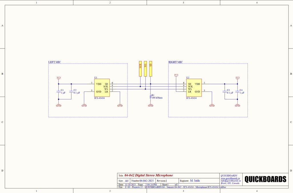
This microphone is specifically engineered for applications requiring high Signal-to-Noise Ratio (SNR) and a wide frequency response in space-constrained environments. The digital interface is highly immune to electromagnetic interference (EMI) and power supply noise, which are frequent challenges in densely packed portable electronics. The stereo configuration shown in this reference block allows two microphones to share a single I2S data line, providing synchronized left and right channel audio for spatial awareness or noise cancellation algorithms.
| Technical Specification | Details |
| Supply Voltage Range | 1.6V to 3.63V |
| Signal-to-Noise Ratio (SNR) | 65 dBA |
| Interface Type | I2C / I2S (24-bit Data) |
| Acoustic Overload Point | 120 dB SPL |
| Supply Current | 230 uA |
| Sensitivity | -26 dB FS |
| Low Frequency Corner | 50 Hz |
| Package Type | 3.25 mm x 2.4 mm x 1.2 mm |
Pin Configuration and Function Mapping
The ICS-43434 utilizes a 6-pin land grid array (LGA) footprint. The pinout is optimized to facilitate easy routing of the three-wire I2S bus.
| Pin Number | Primary Function | Secondary / Peripheral Functions |
| 1 | WS | Word Select / Left-Right Clock |
| 2 | LR | Left/Right Channel Selection |
| 3 | GND | Ground Reference |
| 4 | SCK | Serial Data Clock for I2S Bus |
| 5 | VDD | Positive Power Supply (3.3V) |
| 6 | SD | Serial Data Output (Time-multiplexed) |
Functional Block Analysis & Design Decisions
Power and Decoupling Block
Each microphone (U1 and U2) is supported by a dedicated decoupling network consisting of C1/C4 (1 uF) and C2/C3 (0.1 uF). MEMS microphones are extremely sensitive to supply transients, which can manifest as audible artifacts or “pops” in the digital bitstream. The 0.1 uF ceramic capacitor serves as a high-frequency bypass, chosen for its low equivalent series inductance (ESL) to suppress noise from nearby digital switching. The 1 uF capacitor provides localized bulk storage to stabilize the supply during the microphone’s internal sampling cycles. Ceramic X7R capacitors are specified here for their superior stability across temperature and voltage compared to standard electrolytic types.
Digital Interface and Channel Mapping
The digital core utilizes a three-wire I2S interface: SCK (Serial Clock), WS (Word Select), and SD (Serial Data). In this stereo implementation, the SD line is shared between both devices. To prevent bus contention, the LR pin (Pin 2) is used to assign each microphone to a specific phase of the WS clock. U1 has Pin 2 tied to 3.3V (Logic High), designating it as the “Left” microphone, which drives data on the first half of the WS cycle. U2 has Pin 2 tied to GND (Logic Low), designating it as the “Right” microphone, driving data on the second half of the cycle. When one microphone is driving the bus, the other enters a high-impedance state.
Data Line Termination
A 100k Ohm pulldown resistor (R1) is placed on the SD line. This design rationale is necessary to define the logic state of the serial data bus when both microphones are in high-impedance mode (during the transition periods of the WS clock). Without R1, the high-impedance data line could float, potentially causing the host processor to interpret leakage current as valid audio data, which increases the noise floor of the system.
Placement & Trace Logic
The physical layout of the digital audio bus requires careful attention to clock integrity. SCK and WS should be routed with matched lengths where possible to minimize phase skew. Because this is a bottom port microphone, the PCB must feature an acoustic hole aligned with the sensor’s port. Senior engineers should ensure a solid ground plane is present beneath the sensor and its decoupling capacitors to provide a low-impedance return path, which is vital for maintaining the 65 dBA SNR in the presence of digital switching noise.
Implementation Insights
A primary engineering consideration is the acoustic seal. Since the ICS-43434 is a bottom-port device, the performance is heavily dependent on the mechanical interface between the PCB and the product enclosure. Any air leakage around the port will result in a significant loss of low-frequency sensitivity. Utilizing a specialized acoustic gasket and ensuring a flat, solder-mask-free area around the PCB hole is necessary for optimal capture.
Thermal management during assembly is critical. Excess heat during the reflow process can damage the delicate MEMS membrane or the internal ASIC. It is imperative to follow the manufacturer’s recommended reflow profile and avoid “wash” processes, as liquid or pressurized air entering the acoustic port can permanently degrade the sensor or cause total failure.
The I2S clock speed must be managed relative to the system’s power consumption. While the ICS-43434 supports various sample rates, driving the SCK at high frequencies over long traces can introduce jitter and increase electromagnetic radiation. Using series termination resistors (typically 22 to 47 Ohms) on the clock lines at the host side is recommended for designs where the microphones are located distant from the primary MCU.
Applications
- Smart Speakers and Voice Assistants: High-SNR capture for far-field voice recognition and clear command execution.
- Smartphones and Tablets: Providing compact, high-quality audio recording and environmental noise cancellation.
- Wearable Technology: Integrating discrete audio capture into smartwatches and hearables for voice calls and biometric analysis.
- IoT Environmental Monitoring: Real-time acoustic logging for industrial equipment health monitoring and security systems.
Integrating the ICS-43434 into your design
This modular block provides a production-ready implementation of a digital stereo microphone array, eliminating the uncertainty of I2S bus timing and channel assignment. By utilizing a pre-validated decoupling and termination strategy, this design ensures that the high-resolution 24-bit audio signal remains protected from power supply noise and bus floating. This reusable building block allows engineers to skip basic audio frontend hardware validation and focus immediately on the software-level digital signal processing and acoustic housing design.
Skip the tedious research and manual entry. Download the production-ready schematic block for the ICS-43434 directly from the Quickboards Library.