I3G4250DTR reference schematic design
The I3G4250DTR is a high-performance, low-power three-axis digital output gyroscope. It is engineered to measure angular rates across pitch, roll, and yaw with high stability and accuracy, even in environments subjected to significant temperature fluctuations and mechanical stress. Typically found in industrial applications, robotics, and inertial navigation systems, this IC provides a reliable method for tracking orientation and rotational movement.
Overview of the I3G4250DTR
This gyroscope utilizes a dedicated sensing element and an IC interface capable of providing the measured angular rate to the external world through a standard digital interface (I2C or SPI). The device includes a deep, 32-level first-in, first-out (FIFO) buffer, allowing the host processor to sleep for longer periods while data is collected, significantly reducing overall system power consumption.
| Technical Specification | Details |
| Supply Voltage Range | 2.4V to 3.6V |
| I/O Voltage Range | 1.8V to VDD |
| Measurement Range | Selectable +/- 245, 500, or 2000 dps |
| Communication Protocols | I2C and SPI (3-wire and 4-wire) |
| Embedded Features | FIFO, Temperature Sensor, Power-down mode |
| Sensitivity Drift | +/- 2 percent over temperature |
| Resonant Frequency | 19.3 kHz |
| Current Consumption | 6.1 mA in normal mode |
Pin Configuration and Function Mapping
The I3G4250DTR is housed in a compact 16-pin plastic land grid array (LGA) package. The design organizes digital communication, power, and interrupt logic for modular efficiency.
| Pin Number | Primary Function | Secondary / Peripheral Functions |
| 1 | VDDIO | I/O Power Supply |
| 2 | SCL/SPC | I2C Serial Clock / SPI Serial Port Clock |
| 3 | SDA/SDI/SDO | I2C Serial Data / SPI Serial Data Input |
| 4 | SDO/SA0 | SPI Serial Data Output / I2C Address Selection |
| 5 | CS | Chip Select (I2C/SPI Mode Selection) |
| 6 | DRDY/INT2 | Data Ready / Programmable Interrupt 2 |
| 7 | INT1 | Programmable Interrupt 1 |
| 8-12, 15 | RES | Reserved (Must be connected to GND) |
| 13 | GND | System Ground |
| 14 | PLLFILT | Phase-Locked Loop Filter |
| 16 | VDD | Main Power Supply |
Functional Block Analysis & Design Decisions
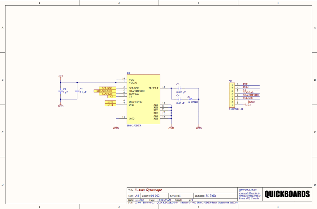
Power and Decoupling Block
The I3G4250DTR features a dual-supply architecture. VDD (Pin 16) powers the internal analog and sensing circuitry, while VDDIO (Pin 1) defines the logic level for the digital communication pins. In this design, both are tied to a 3.3V rail. Stability is maintained via C1 (1uF) and C2 (0.1uF) ceramic capacitors. The 0.1uF capacitor is a high-frequency bypass component, selected for its low equivalent series inductance (ESL) to filter out high-speed switching noise generated by the digital interface. The 1uF capacitor acts as a localized reservoir to handle low-frequency transients. These should be placed with maximum proximity to the VDD/VDDIO pins to minimize trace parasitic effects.
Signal Conditioning and PLL Filtering
A critical sub-circuit in this design is the Phase-Locked Loop (PLL) filter connected to Pin 14. This network, consisting of C3 (0.012uF), C4 (0.47uF), and R1 (10k Ohms), is essential for the stability of the internal clock generation. The angular rate measurement relies on precise timing of the sensing element’s vibration; jitter or instability in the internal PLL will manifest as increased noise or drift in the rotational data. These values are selected based on the manufacturer’s requirements for the internal control loop stability. Senior engineers should ensure these components are placed away from high-speed digital traces to prevent noise injection into the PLL.
Grounding and Digital Integration
Pins 8 through 12 and Pin 15 are reserved pins that must be tied to Ground (GND) to ensure the internal IC references are correctly biased and to improve the mechanical thermal path of the LGA package. The digital interface (Pins 2-5) is routed to header X1, providing flexibility for the host microcontroller to select between I2C or SPI. Pin 5 (CS) defines the mode: pulling it high or leaving it high defaults the IC to I2C, while pulling it low enables SPI communication.
Implementation Insights
Mechanical layout is as critical as electrical connectivity for a gyroscope. Because the I3G4250DTR measures micro-mechanical vibrations of an internal silicon structure, the PCB itself acts as part of the sensing system. Mounting the sensor near heat-generating components or high-vibration areas (like cooling fans or motors) can introduce significant zero-rate level offsets.
A standard requirement for high-resolution motion sensing is the isolation of the ground plane beneath the sensor. A solid ground plane provides shielding, but designers should avoid routing high-current digital return paths through the area directly under the gyroscope to prevent electromagnetic interference from coupling into the sensing element.
The interrupts (INT1 and INT2) should be utilized to implement an event-driven firmware architecture. By configuring the IC to trigger INT1 when new data is available or when a specific angular rate threshold is exceeded, the host microcontroller can remain in a low-power state, wake up only to process the data, and then return to sleep, maximizing battery life in portable applications.
Applications
- Industrial Robotics: Providing real-time orientation data for robotic arms and autonomous mobile robots (AMRs) to ensure precise movement and stabilization.
- Inertial Navigation Systems (INS): Acting as a core component in dead-reckoning systems for vehicles or drones when GPS signals are unavailable.
- Vibration Monitoring: Detecting and measuring high-frequency rotational vibrations in industrial machinery to predict maintenance needs.
- Human-Machine Interfaces: Enabling gesture control and motion tracking in specialized industrial handheld tools and wearable equipment.
Integrating the I3G4250DTR into your design
This modular block provides a production-ready implementation of a high-precision digital gyroscope. By incorporating the pre-validated PLL filter network and supply decoupling strategy, this design eliminates the uncertainty associated with internal timing stability and power-related noise. This reusable building block allows engineers to skip basic hardware validation and focus on sensor fusion algorithms and system-level orientation tracking.
Skip the tedious research and manual entry. Download the production-ready schematic block for the I3G4250DTR directly from the Quickboards Library.