FT232RNL USB to UART Bridge Reference Schematic Design
The FT232RNL is a specialized USB-to-serial UART interface integrated circuit designed by FTDI. Its primary function is to provide a seamless bridge between a USB host and a microcontroller or peripheral via a serial interface. By integrating an internal oscillator, EEPROM, and a complete USB protocol stack, it eliminates the need for external crystals and complex firmware development. This IC is commonly utilized in USB-to-RS232/RS485 converters, industrial control systems, and as a programming/debugging interface for microcontrollers.
Overview of the FT232RNL
The FT232RNL is a “Full Speed” USB 2.0 device that operates at 12 Mbps. It supports a wide range of baud rates and provides high-level integration, including level-shifting capabilities via a dedicated VCCIO pin. This allows the UART interface to communicate with logic levels ranging from 1.8V to 5V.
| Technical Specification | Value |
| USB Protocol | USB 2.0 Full Speed |
| UART Baud Rates | 300 baud to 3 Mbaud |
| Supply Voltage (VCC) | 3.3V to 5.25V |
| I/O Voltage (VCCIO) | 1.8V to 5.25V |
| Operating Current | 15 mA (typical) |
| Internal EEPROM | 1024 bit |
| Package Type | 28-pin SSOP / 32-pin QFN |
Pin Configuration and Function Mapping
The following mapping describes the primary connections utilized in this modular block to ensure a robust USB-to-UART bridge.
| Pin Number | Primary Function | Secondary / Peripheral Functions |
| 1 | TXD | Transmit Asynchronous Data Output |
| 5 | RXD | Receive Asynchronous Data Input |
| 3 | RTS# | Request to Send Control Output / Handshake |
| 11 | CTS# | Clear to Send Control Input / Handshake |
| 15 | USBDP | USB Data Plus |
| 16 | USBDM | USB Data Minus |
| 20 | VCC | Device Power Supply |
| 4 | VCCIO | Power for UART Interface Pins |
| 17 | 3V3OUT | 3.3V Internal Regulator Output |
| 19 | RESET# | Active Low Reset Input |
Functional Block Analysis & Design Decisions
Power and Decoupling Strategy
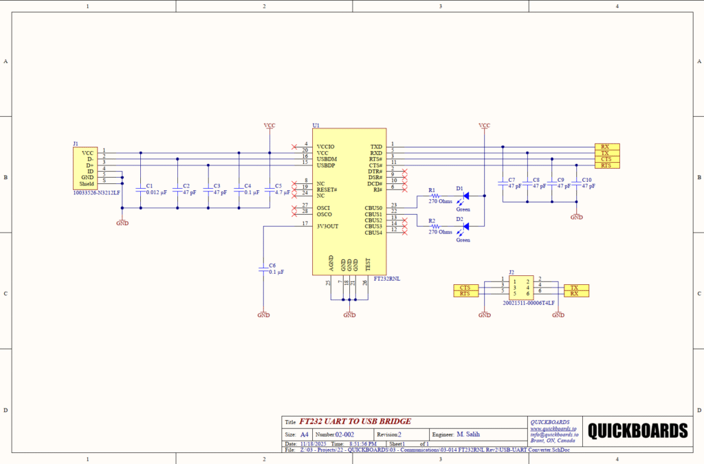
The design utilizes a multi-stage decoupling and filtering network on the VCC rail (Pin 20) to maintain power integrity over the USB bus. A bulk 4.7uF ceramic capacitor (C5) serves as a local reservoir to handle low-frequency transients, while a 0.1uF capacitor (C4) provides mid-frequency bypassing. Higher frequency noise suppression is achieved through C1 (0.012uF) and the 47pF capacitors (C2, C3) positioned near the USB connector. For high-speed interface designs, Ceramic X7R or X5R types are preferred due to their low equivalent series resistance (ESR) and stability over temperature. The 3V3OUT (Pin 17) provides an internal regulated voltage and requires a 0.1uF capacitor (C6) to ensure the stability of the internal oscillator and USB transceiver logic.
Signal Conditioning and EMI Mitigation
The UART interface lines (TXD, RXD, RTS#, CTS#) are equipped with 47pF ceramic capacitors (C7, C8, C9, C10) tied to ground. These components act as low-pass filters to suppress high-frequency harmonics and electromagnetic interference (EMI) that can be radiated from the serial traces. This is particularly important in industrial environments where data integrity is paramount. These capacitors should be placed as close to the IC pins as possible to minimize the loop area of high-speed signals. The USB data lines (USBDP and USBDM) are routed directly from the J1 connector to pins 15 and 16, following differential pair routing requirements to maintain 90 Ohm impedance.
Status Indication
The design incorporates visual feedback through two green LEDs (D1, D2). These are driven by the Configurable Bus (CBUS) pins, specifically CBUS0 and CBUS1. In the default configuration, these pins act as TXLED# and RXLED# indicators, flashing during data transmission. 270 Ohm resistors (R1, R2) are placed in series to limit the current through the LEDs. This value is calculated to provide sufficient brightness while keeping the current draw well within the 10mA source/sink capability of the FT232RNL I/O pins.
Implementation Insights
A primary design consideration is the connection of VCCIO (Pin 4). In this schematic, VCCIO is tied to the main VCC rail, setting the UART logic levels to 5V. If the target microcontroller operates at 3.3V, VCCIO must be disconnected from VCC and tied to the 3.3V power rail of the microcontroller to prevent overvoltage damage to the peripheral.
High-level integration requires careful grounding. The schematic shows both AGND (Pin 25) and standard GND pins (7, 18, 21, 26) tied to a common ground plane. To prevent USB noise from entering the analog portions of the chip, a solid, low-impedance ground plane is essential. Furthermore, the USB shield on J1 is grounded through a separate path or filtered to prevent EMI from the cable shield from injecting noise into the signal ground.
Applications
- USB to RS232 / RS422 / RS485 Converters: Converts traditional serial communication protocols to USB for modern computer interfacing.
- Legacy Peripheral Upgrades: Allows older hardware designed for COM ports to be modernized with USB connectivity without redesigning the core logic.
- Microcontroller Debugging Ports: Provides a reliable method for serial terminal debugging and firmware updates over a standard USB cable.
- USB Industrial Control: Facilitates robust communication between industrial PLCs or sensors and a central monitoring station via USB.
Integrating the FT232RNL into your design
This modular block simplifies the addition of USB connectivity by providing a pre-validated layout for power filtering and signal integrity. By utilizing the internal regulator and oscillator of the FT232RNL, this circuit minimizes the Bill of Materials (BOM) and reduces PCB real estate. The inclusion of status LEDs and EMI filtering ensures a professional and robust implementation that meets modern certification standards for connectivity.
Skip the tedious research and manual entry. Download the production-ready schematic block for the FT232RNL directly from the Quickboards Library.