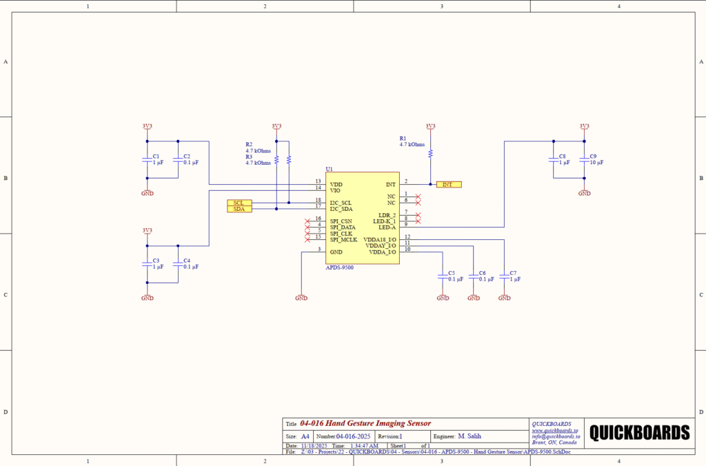
APDS-9500 Hand Gesture Imaging Sensor Reference Schematic Design
The APDS-9500 is a highly integrated hand gesture recognition sensor that utilizes an imaging-based approach to detect and interpret complex movements. Unlike simple proximity-based gesture sensors, the APDS-9500 features an integrated imaging array and digital signal processing (DSP) engine capable of recognizing nine distinct gestures, including swiping in four directions, rotating, and waving. Its primary function is to enable touchless human-machine interfaces (HMI) in environments where physical contact is impractical or undesirable. This device is frequently found in automotive infotainment systems, smart home controllers, and industrial equipment where operators may be wearing gloves.
Overview of the APDS-9500
The APDS-9500 operates by illuminating the field of view with an infrared LED and capturing the reflected light through its internal imaging sensor. The onboard processor analyzes the frame-to-frame changes to determine the gesture. It supports two primary communication modes: an I2C interface for standard gesture output and an SPI interface for high-speed imaging data. In this reference design, the sensor is configured for I2C operation to streamline integration with standard 3.3V microcontrollers while utilizing an interrupt-driven architecture to minimize host CPU overhead.
| Feature | Specification |
| Supply Voltage (VDD) | 2.8V to 3.3V |
| I/O Voltage (VIO) | 1.8V to 3.3V |
| Communication Interface | I2C (up to 400 kHz) and SPI |
| Gesture Recognition | 9 distinct gestures |
| Integrated LED Driver | Yes, up to 200 mA |
| Detection Range | 10 cm to 60 cm |
| Operating Temperature | -20 to 70 Celsius |
| Current Consumption | 5 mA (Typical Operating) |
Pin Configuration and Function Mapping
The APDS-9500 is housed in a multi-pin package that requires careful routing to separate the sensitive analog rails from the high-current LED driver path.
| Pin Number | Primary Function | Secondary / Peripheral Functions |
| 2 | INT | Interrupt Output (Active Low) |
| 3 | GND | System Ground |
| 9 | LED-A | Infrared LED Anode Connection |
| 10 | VDDA_I/O | Internal Analog Rail Decoupling |
| 11 | VDDAY_I/O | Internal Analog Rail Decoupling |
| 12 | VDDA18_I/O | Internal 1.8V Regulator Decoupling |
| 13 | VDD | Main Supply Voltage (3.3V) |
| 14 | VIO | I/O Supply Voltage (3.3V) |
| 17 | I2C_SDA | I2C Serial Data |
| 18 | I2C_SCL | I2C Serial Clock |
| 1, 6, 7, 8 | NC | No Internal Connection |
| 4, 5, 15, 16 | SPI_DATA / CSN | SPI Interface (Not Used in this Block) |
Functional Block Analysis & Design Decisions
Power Supply and Multi-Rail Decoupling
The APDS-9500 utilizes a sophisticated internal power architecture that requires multiple stages of decoupling to maintain imaging integrity. The main VDD (Pin 13) and VIO (Pin 14) rails are decoupled with a tiered capacitor approach: 1 uF (C1, C3) for bulk energy storage and 0.1 uF (C2, C4) for high-frequency bypass. This design rationale is critical for imaging sensors, where high-frequency noise on the supply can manifest as “ghosting” or artifacts in the gesture recognition engine. Additionally, the internal regulators for the analog and digital cores (Pins 10, 11, 12) require dedicated capacitors (C5, C6, C7). X7R ceramic capacitors are specified for their superior temperature stability and low equivalent series resistance (ESR) compared to electrolytic or Y5V alternatives.
Host Interface and Interrupt Logic
Communication is handled via the I2C bus (Pins 17, 18). This block utilizes 4.7 kOhm pull-up resistors (R2, R3) tied to the 3.3V rail. This resistance value is the industry standard for 400 kHz Fast-mode I2C, providing a balanced rise time that compensates for bus capacitance while maintaining low static current draw. A third 4.7 kOhm pull-up (R1) is applied to the INT pin (Pin 2). By using an interrupt-driven approach, the sensor signals the host MCU only when a valid gesture or proximity event occurs, allowing the host to remain in a low-power sleep state during idle periods.
Illumination and LED Drive Path
The LED-A connection (Pin 9) is responsible for driving the external infrared LED used for imaging. This node is supported by C8 (1 uF) and C9 (10 uF) capacitors. The inclusion of the 10 uF capacitor (C9) is a senior-level design requirement; during gesture detection, the LED is pulsed with high currents (up to 200 mA). Without the localized bulk capacitance of C9, these current spikes would cause significant voltage droop on the 3.3V rail, potentially resetting the host microcontroller or interfering with other sensitive analog sensors in the system.
Placement & Trace Logic
The physical layout must prioritize the proximity of C5, C6, and C7 to their respective internal regulator pins (10, 11, and 12). These capacitors define the stability of the imaging array’s power envelope. Trace logic for the I2C lines should be kept away from the LED-A path to prevent inductive coupling of the high-current LED pulses into the digital communication lines. A solid ground plane beneath Pin 3 is essential for minimizing the return path impedance for the imaging DSP.
Implementation Insights
A primary engineering consideration for the APDS-9500 is the optical integration. The sensor must be placed behind an infrared-transparent window, typically made of polycarbonate or acrylic with an IR-pass coating. If the window material attenuates too much of the 850nm-940nm spectrum, the gesture detection range will be significantly reduced. Furthermore, internal “crosstalk”—where light from the IR LED reaches the sensor directly through the device enclosure without reflecting off the hand—must be prevented using opaque mechanical baffles.
When integrating this block into a multi-sensor system, ensure that the I2C address does not conflict with other peripherals. The APDS-9500 typically resides at a fixed address, and bus arbitration must be managed carefully if high-speed image data is being pulled from the device, as this can saturate the bus bandwidth.
The LED pulse current is programmable via internal registers. Senior engineers should verify that the 3.3V regulator in the parent system has sufficient transient response to handle the peak current pulses of the IR LED, even with the 10 uF bulk capacitor in place. Failure to account for this can lead to electromagnetic interference (EMI) issues during FCC or CE compliance testing.
Applications
- Automotive Infotainment: Enabling drivers to skip tracks, adjust volume, or navigate menus without taking their eyes off the road.
- Smart Home Panels: Touchless control of thermostats and lighting systems to prevent the spread of germs in kitchens or bathrooms.
- Industrial HMI: Allowing operators in cleanrooms or heavy machinery environments to interact with displays while wearing protective gear.
- Touchless Kiosks: Implementing hygienic user interfaces in public transportation or retail environments.
Integrating the APDS-9500 into your design
This modular reference block provides a pre-validated, high-integrity hardware environment for the APDS-9500 gesture sensor. By utilizing a comprehensive multi-rail decoupling strategy and an optimized LED drive path, this design eliminates the uncertainty associated with power-induced imaging noise and system-level voltage transients. This production-ready sub-system allows engineering teams to skip the foundational hardware bring-up and focus immediately on the software integration and optical housing challenges inherent in gesture-based interfaces.
Skip the tedious research and manual entry. Download the production-ready schematic block for the APDS-9500 directly from the Quickboards Library.