8-Channel Passive High Pass Filter reference schematic design
The 09-002 is a versatile 8-channel passive signal conditioning block designed for high-precision first-order high-pass filtering. Unlike active filter topologies that require a dedicated power supply and can introduce operational amplifier noise or DC offsets, this passive RC (Resistor-Capacitor) network provides high-reliability frequency discrimination with zero power consumption. This block is primarily used for AC coupling, removing unwanted DC offsets from sensor signals, and suppressing low-frequency “rumble” or interference in high-speed data acquisition systems.
Overview of the 8-Channel Passive High Pass Filter
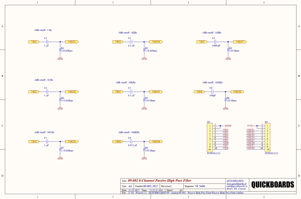
This schematic block features eight independent channels with cutoff frequencies spanning seven decades, from 1 Hz to 10 MHz. By utilizing a series capacitor and a shunt resistor to ground, the circuit allows high-frequency signals to pass with minimal attenuation while providing a -20 dB per decade roll-off for frequencies below the corner frequency. It acts as a fundamental building block for engineers who need to stabilize signal baselines or protect sensitive analog-to-digital converter (ADC) inputs from low-frequency transients.
| Feature | Specification |
| Filter Topology | 1st Order Passive High-Pass (RC) |
| Channel Count | 8 Independent Channels |
| Cutoff Frequency Range | 1 Hz to 10 MHz |
| Attenuation Rate | -20 dB / decade |
| Input Interface | 10-pin Header (X1) |
| Output Interface | 10-pin Header (X2) |
| Power Consumption | 0 Watts (Passive) |
Pin Configuration and Function Mapping
The 09-002 utilizes a standardized dual-header configuration to facilitate seamless integration into modular hardware stacks.
| Pin Number | Primary Function | Secondary / Peripheral Functions |
| X1-1, X1-2 | GND | System Ground Reference |
| X1-3 to X1-10 | VIN1 to VIN8 | Filter Inputs (Channel 1 through 8) |
| X2-1 | 3V3 | Modular Power Rail (Pass-through) |
| X2-2 | GND | System Ground Reference |
| X2-3 to X2-10 | VOUT1 to VOUT8 | Filter Outputs (Channel 1 through 8) |
Functional Block Analysis & Design Decisions
Passive Signal Conditioning (High-Pass Topology)
The core of this design is the Signal Conditioning block, implemented via a series-capacitive, shunt-resistive topology. This specific arrangement is chosen for its simplicity and inherent stability. In an AC-coupled system, the series capacitor blocks any DC component while the resistor provides a return path to ground, defining the input impedance of the stage. This prevents downstream high-impedance inputs, such as those on a CMOS microcontroller, from floating and becoming susceptible to environmental noise.
Component Selection and Frequency Scaling
Component values are meticulously selected to provide exact decade and sub-decade cutoff frequencies based on the formula f = 1 / (2 * pi * R * C). For lower frequency channels (1 Hz to 100 Hz), 1uF capacitors (C1, C4, C7) are used in conjunction with high-value resistors (158k, 15.8k, 1.58k). For high-frequency channels (1 MHz to 10 MHz), the capacitance is scaled down to 1000pF and 100pF. For these high-frequency paths, C0G/NP0 ceramic capacitors are preferred over standard X7R types because of their superior temperature stability and lower voltage coefficient, ensuring the filter pole does not shift during operation. Resistors are selected from the E96 1% series to maintain tight tolerance on the -3dB point.
Placement and Trace Logic
The physical layout requires the series capacitor to be placed near the input header (X1) to block DC at the entry point, while the shunt resistor is placed closer to the output header (X2). This minimizes the amount of PCB trace area that carries a signal with a DC offset, reducing potential leakage current paths. For the 1 MHz and 10 MHz channels, trace lengths must be kept extremely short and of uniform width to minimize parasitic inductance, which could otherwise create an unintentional resonant LC circuit that would distort the filter’s roll-off characteristics.
Design Rationale: Impedance and Baseline Stability
The 158-ohm resistors (R5, R6, R8) used in the high-frequency channels provide a low-impedance path to ground. This is a deliberate design choice to ensure fast discharging of the series capacitor, which is essential when the filter is used to recover small AC signals after a large DC transient. In the 1 Hz channel, the 158k resistor (R1) is used; this high value is necessary to achieve the ultra-low cutoff frequency with a standard 1uF capacitor, though it requires the following stage to have a significantly higher input impedance (ideally > 1.5M ohms) to avoid loading the filter and shifting the cutoff frequency upward.
Implementation Insights
A primary engineering consideration when using passive high-pass filters is the “Loading Effect.” Because the filter is passive, its performance is dependent on the input impedance of the device it is driving. If the 09-002 is connected to a low-impedance load, the load acts in parallel with the shunt resistor, effectively lowering the resistance value and increasing the cutoff frequency. It is standard practice to buffer the output of these filters with a high-impedance operational amplifier if precision frequency response is required.
Another consideration involves the voltage rating of the series capacitors. Since the capacitor blocks the entire DC offset of the input signal, its voltage rating must exceed the maximum potential DC rail of the system. For this 3.3V-standard block, 10V to 16V rated capacitors are recommended to provide sufficient derating and ensure long-term reliability.
The 10 MHz channel is particularly sensitive to parasitic capacitance. Layout engineers should ensure a clear ground plane keep-out area directly beneath the series capacitor (C6) and its associated pads to prevent stray capacitance from creating a secondary low-pass pole that would roll off high-frequency data prematurely.
Applications
- AC Coupling: Removing the DC bias from a signal so it can be re-centered around a specific reference voltage for ADC sampling.
- Rumble Filtering: Eliminating low-frequency mechanical vibrations or 50/60 Hz mains hum from sensitive sensor measurements.
- Signal Baseline Restoration: Rapidly recovering the AC portion of a signal following a large, slow-moving baseline shift or DC offset.
- EMI Suppression: Acting as a front-end filter to block low-frequency electromagnetic interference while preserving high-speed data transitions.
integrating the 09-002 into your design
The 09-002 8-Channel Passive High Pass Filter block provides a production-ready, pre-validated solution for managing DC offsets and low-frequency noise. By offering a range of cutoff frequencies that cover the entire typical analog signal spectrum, this modular block eliminates the need for manual RC calculations and component sourcing. It allows engineers to focus on high-level system logic while ensuring that the critical signal conditioning stages are robust, stable, and power-efficient.
Skip the tedious research and manual entry. Download the production-ready schematic block for the 09-002 directly from the Quickboards Library.