8-Channel Passive Low Pass Filter Reference Schematic Design
The 09-001 is a modular 8-channel passive signal conditioning block designed to provide high-precision first-order low-pass filtering across a wide spectrum of frequencies. Rather than utilizing active components that introduce power requirements and potential DC offsets, this passive RC (Resistor-Capacitor) array focuses on simplicity, reliability, and frequency accuracy. It is typically employed as an anti-aliasing stage for Analog-to-Digital Converters (ADCs), a noise suppression filter for industrial sensors, or a signal smoothing block for Pulse Width Modulation (PWM) to DC conversion.
Overview of the Passive Low Pass Filter
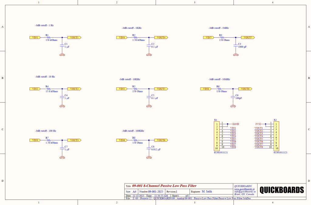
This schematic block features eight independent channels, each tuned to a specific -3dB cutoff frequency ranging from 1 Hz up to 10 MHz. By utilizing high-precision resistors and stable ceramic capacitors, the 09-001 ensures that signal integrity is maintained while unwanted high-frequency noise is shunted to ground. Its passive nature makes it inherently stable and suitable for low-power or battery-operated systems where every microampere of quiescent current matters.
| Feature | Specification |
| Filter Topology | Passive RC (First-Order) |
| Channel Count | 8 Independent Channels |
| Frequency Range | 1 Hz to 10 MHz |
| Roll-off Rate | -20 dB per decade |
| Input Impedance | 158 Ohms to 158 kOhms |
| Connector Type | Dual 10-pin Headers (X1, X2) |
| Signal Swing | Limited only by component voltage ratings |
Pin Configuration and Function Mapping
The 09-001 utilizes two 10-pin headers to facilitate easy integration between a signal source and a downstream processor or ADC.
| Pin Number | Primary Function | Secondary / Peripheral Functions |
| X1-3 to X1-10 | VIN1 to VIN8 | Filter Input (Channel 1 to 8) |
| X2-3 to X2-10 | VOUT1 to VOUT8 | Filter Output (Channel 1 to 8) |
| X1-1, X1-2 | GND | System Ground Reference |
| X2-1 | 3V3 | Optional Logic/Reference Supply |
| X2-2 | GND | System Ground Reference |
| X1-9, X1-10 | VIN7, VIN8 | High-Frequency Filter Inputs |
Functional Block Analysis & Design Decisions
Signal Conditioning: First-Order RC Networks
The primary functional block of this design is the Signal Conditioning array. Each channel consists of a series resistor and a shunt capacitor to ground. This topology creates a single-pole filter where frequencies above the cutoff point are attenuated at a rate of 20 dB per decade. The choice of a passive first-order filter is driven by the need for zero-power operation and the avoidance of the non-linearity or noise floor issues often associated with operational amplifiers in active filter designs.
Component Selection: Precision and Stability
The resistors used (R1 through R8) are selected from the E96 series (e.g., 158 Ohms, 1.58 kOhms, 158 kOhms) to achieve precise decade and sub-decade cutoff frequencies based on the formula f = 1 / (2 * pi * R * C). For lower frequency channels (1 Hz to 100 Hz), 1 uF capacitors are utilized to keep resistor values within a manageable range that avoids excessive thermal noise. For high-frequency channels (1 MHz to 10 MHz), resistor values are dropped to 158 Ohms to minimize the effects of parasitic trace capacitance and ensure the pole remains dominant. Capacitors for high-frequency channels (100 pF and 1000 pF) should be C0G/NP0 ceramic types for their near-zero temperature coefficient and lack of piezoelectric “singing.”
Placement & Trace Logic
The physical layout of this block requires the capacitors (C1 through C8) to be placed as close as possible to the output header (X2) or the destination ADC pins. This prevents the output traces from acting as antennas that pick up high-frequency electromagnetic interference (EMI) after the filtering has occurred. Ground traces must be wide and provide a low-impedance path to the main ground plane to ensure that shunted noise does not create ground bounce in the system.
Design Rationale: Impedance Matching and Pole Definition
The resistors in this circuit serve two purposes: they define the filter pole and provide a degree of protection for downstream CMOS inputs by limiting transient currents. For the 1 Hz channel, a 158 kOhm resistor is used; while this provides excellent filtering, senior engineers must account for the leakage current of the following stage, as a high-impedance series resistor can induce a significant DC voltage drop if the load impedance is not sufficiently high.
Implementation Insights
When integrating the 09-001 into a larger system, the source and load impedances must be carefully evaluated. Passive RC filters are sensitive to “loading.” If the input impedance of the next stage (e.g., an ADC without an internal buffer) is comparable to the filter’s series resistor, the cutoff frequency will shift, and the signal amplitude will be attenuated by the resulting voltage divider.
For the high-frequency channels (10 MHz), parasitic board capacitance can significantly lower the actual cutoff frequency. Using a ground plane “keep-out” area directly under the signal traces of the 10 MHz channel can help maintain the intended 158 Ohms to 100 pF ratio by reducing stray capacitance.
Applications
- Anti-Aliasing for ADCs: Removing frequencies above the Nyquist limit to prevent signal distortion during sampling.
- Sensor Noise Reduction: Filtering out 50/60 Hz mains hum or high-frequency switching noise from industrial sensors.
- PWM Signal Smoothing: Converting a digital PWM output into a stable analog DC voltage for reference or control.
- Data Line EMI Filtering: Protecting sensitive communication lines from environmental electromagnetic interference.
Integrating the 09-001 Passive Low Pass Filter into your design
The 09-001 Passive Low Pass Filter block offers a production-ready solution for managing signal integrity across eight independent channels. By providing pre-calculated RC pairs that span seven decades of frequency, this modular block eliminates the tedious math and component sourcing associated with basic signal conditioning. Its passive architecture ensures that it can be dropped into any design without increasing the power budget or introducing active-component noise.
Skip the tedious research and manual entry. Download the production-ready schematic block for the 09-001 Passive Low Pass Filter directly from the Quickboards Library.