MLX90393SLW 3-Axis Magnetometer Reference Schematic Design
The MLX90393SLW is a high-precision 3-axis magnetic field sensor designed for low-power, contactless sensing applications. Utilizing Melexis patented Triaxis technology, this integrated circuit is capable of sensing magnetic flux density along the X, Y, and Z axes with 16-bit resolution. It is commonly implemented in human-machine interfaces (HMI) such as joysticks and rotary knobs, anti-tamper sensors for utility meters, and electronic compasses for portable navigation devices. Its ability to be reprogrammed for different duty cycles and resolutions makes it an extremely versatile component for both static and dynamic magnetic field sensing.
Unlock the Quickboards Library
Get instant access to this Altium Schematic and hundreds of other subcircuits. Hardware design, modularized. Schematic + Layout + Firmware. Built to IPC standards for zero re-spins.
| Technical Specification | Value |
| Supply Voltage (VDD/VDDIO) | 2.2V to 3.6V |
| Resolution | 16-bit ADC |
| Communication Protocols | I2C and SPI |
| Magnetic Full-Scale Range | 5 mT to 50 mT (Programmable) |
| Current Consumption | 100 microamps at 10 Hz (Typical) |
| Operating Temperature | -40 to 85 Celsius |
| Unique Feature | Integrated Temperature Sensor |
| Measurement Rate | Up to 1 kHz (depending on mode) |
Pin Configuration and Function Mapping
The MLX90393SLW is housed in a compact QFN package. The pinout provided in this reference design facilitates either I2C or SPI communication modes, depending on the logic state of the selection pin.
| Pin Number | Primary Function | Secondary / Peripheral Functions |
| 1 | INT | Interrupt Output |
| 2 | MS/CS | Mode Select (I2C/SPI) / Chip Select |
| 3 | SCL/SCK | I2C Serial Clock / SPI Clock |
| 5 | SDA/MOSI | I2C Serial Data / SPI Master Out Slave In |
| 6 | MISO | SPI Master In Slave Out |
| 7 | INT/TRIG | External Trigger Input / Interrupt Output |
| 8 | VDDIO | Digital I/O Power Supply |
| 11 | A1 | I2C Address Bit 1 |
| 12 | A0 | I2C Address Bit 0 |
| 13 | VSS | Ground Reference |
| 15 | VDD | Analog Power Supply |
| 4, 9, 10, 14, 16 | NC | No Internal Connection |
Functional Block Analysis & Design Decisions
Power and Decoupling Strategy
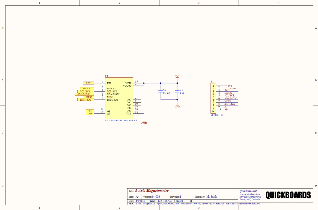
The schematic employs a standard decoupling network for the VDD and VDDIO rails, which are tied to the 3.3V (3V3) system supply in this block. Stability is maintained using a parallel combination of C1 (1 microfarad) and C2 (0.1 microfarads). The 0.1 microfarad capacitor is selected as a high-frequency bypass component to suppress fast switching transients and electromagnetic interference (EMI). The 1 microfarad capacitor provides localized bulk capacitance to stabilize the supply during the sensor’s measurement phases, where current consumption may spike briefly. Ceramic X7R capacitors are utilized for their high volumetric efficiency and stability across the industrial temperature range.
Digital Interface and Address Selection
The block is designed for maximum bus flexibility. The inclusion of A0 and A1 address bits on the breakout connector allows for up to four MLX90393 devices to reside on a single I2C bus. This is critical for multi-sensor arrays or systems requiring redundant measurements. The MS/CS pin (Pin 2) is broken out to allow the host controller to hardware-select between I2C and SPI modes. The dual interrupt pins (INT and INT/TRIG) are provided to support both event-driven data ready signals and external trigger-based sampling, enabling precise synchronization with other inertial or position sensors in the system.
Placement and Trace Logic
Physical layout for the MLX90393SLW requires careful consideration of magnetic environments. The decoupling capacitors C1 and C2 must be placed as close as possible to Pin 8 and Pin 15 to minimize trace inductance. Senior engineers should ensure that no high-current traces or ferrous materials are located directly beneath or immediately adjacent to the sensor, as these will introduce “hard iron” and “soft iron” distortions. Providing a solid ground plane on Pin 13 (VSS) is essential for minimizing return path noise, which can directly impact the sensitivity and noise floor of the 16-bit magnetic measurements.
Implementation Insights
A primary engineering consideration for the MLX90393SLW is the distinction between hard-iron and soft-iron interference. Hard-iron interference, caused by permanent magnets or magnetized metal on the PCB, introduces a constant offset to the sensor readings. Soft-iron interference, caused by nearby materials that distort the magnetic field, creates a non-linear scaling error. Integration of this block into a larger system requires a calibration routine at the firmware level to nullify these effects once the PCB is mounted in its final enclosure.
When using the I2C interface, ensure that pull-up resistors are present on the SCL and SDA lines elsewhere in the system. The MLX90393SLW does not include internal pull-ups. Furthermore, while VDD and VDDIO are tied together in this reference design for simplicity, they can be separated if the host controller operates at a different logic level (e.g., 1.8V), provided both remain within the specified 2.2V to 3.6V range.
A common oversight is the orientation of the sensor relative to the magnetic source. Hall effect sensors are directional; the MLX90393SLW is a Triaxis device, but its sensitivity may vary slightly between the Z-axis (perpendicular to the chip) and the X/Y axes (parallel to the chip). Mechanical alignment should be strictly controlled during assembly to maintain cross-axis consistency.
Applications
- Contactless Joysticks and Gimbals: Provides high-resolution 3D position sensing without mechanical wear and tear, ideal for industrial controls and gaming.
- Anti-Tamper Sensors: Detecting external magnetic fields used to influence or stop utility meters (water, gas, electricity).
- Rotary and Linear Position Sensing: Measuring the position of a magnet attached to a rotating shaft or sliding mechanism for industrial automation.
- Electronic Compasses: Providing orientation data for drones, robotic platforms, and handheld navigation devices.
integrating the MLX90393SLW into your design
This modular schematic block simplifies the implementation of high-resolution magnetic sensing by providing a pre-validated power and communication architecture. By using this building block, engineers can eliminate the uncertainty associated with decoupling capacitor selection and pin mapping for the Triaxis IC. This reusable sub-system allows design teams to focus on sensor fusion and calibration algorithms rather than low-level hardware bring-up.
Skip the tedious research and manual entry. Download the production-ready schematic block for the MLX90393SLW directly from the Quickboards Library.