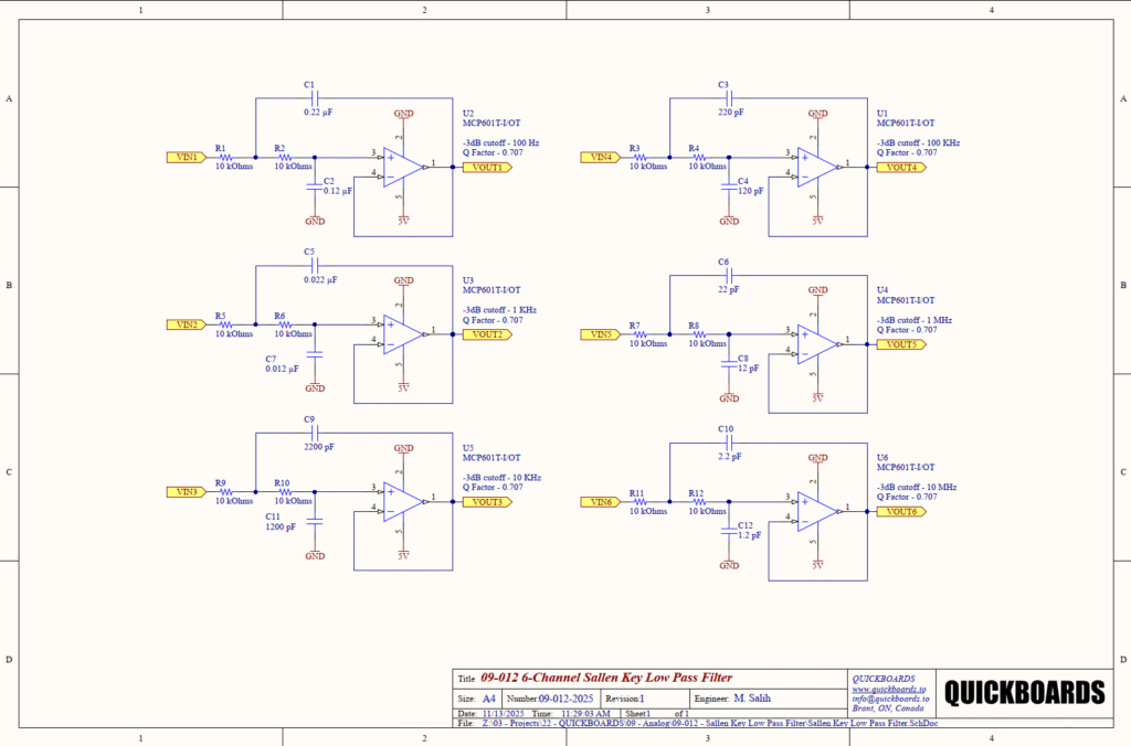
MCP601T-I/OT 6 Channel Sallen Key Low Pass Filter Reference Schematic Design
The MCP601T-I/OT is a low-power, rail-to-rail output operational amplifier characterized by its 2.8 MHz Gain-Bandwidth Product (GBWP) and low quiescent current. Developed by Microchip Technology, this integrated circuit is a staple in portable instrumentation and sensor signal conditioning due to its ability to operate on a single supply voltage as low as 2.7V. In this reference design, the IC is utilized as the active element in a 6-channel Sallen-Key low-pass filter array, providing high-order filtering with minimal component count and high input impedance.
Unlock the Quickboards Library
Get instant access to this Altium Schematic and hundreds of other subcircuits. Hardware design, modularized. Schematic + Layout + Firmware. Built to IPC standards for zero re-spins.
Overview of the MCP601T-I/OT
The MCP601 acts as a unity-gain stable amplifier, making it ideal for the Sallen-Key topology where stable, predictable gain is required for accurate frequency response. Its rail-to-rail output swing allows the signal to occupy nearly the entire supply range, which is critical in low-voltage systems to maintain a high Signal-to-Noise Ratio (SNR). Typical applications include automotive electronics, industrial control systems, and battery-powered medical devices.
| Technical Specification | Value |
| Operating Voltage Range | 2.7V to 6.0V |
| Gain-Bandwidth Product | 2.8 MHz |
| Slew Rate | 2.3 V/us |
| Typical Quiescent Current | 230 uA |
| Input Offset Voltage | 2 mV (Maximum) |
| Output Type | Rail-to-Rail |
| Phase Margin | 50 degrees |
| Package | 5-Lead SOT-23 |
Pin Configuration and Function Mapping
The MCP601T-I/OT is housed in a space-saving SOT-23 package, facilitating high-density PCB layouts for multi-channel filtering systems.
| Pin Number | Primary Function | Secondary / Peripheral Functions |
| 1 | VOUT | Analog Output / Feedback Node |
| 2 | VSS | Negative Power Supply / Ground |
| 3 | VIN+ | Non-inverting Input (Filter Input) |
| 4 | VIN- | Inverting Input (Unity Gain Feedback) |
| 5 | VDD | Positive Power Supply (5V) |
Functional Block Analysis & Design Decisions
Signal Conditioning: 2nd Order Active Sallen-Key Filter
The primary functional block in this schematic is the 2nd Order Sallen-Key Low Pass Filter. This topology was selected because it provides a non-inverting output with high input impedance, preventing the filter from loading the preceding signal source. Each channel is configured for a Butterworth response, indicated by the Q-Factor of 0.707. This design choice ensures a maximally flat passband with no ripples before the cutoff frequency, which is essential for data acquisition systems where amplitude accuracy is paramount.
Technical Deep-Dive: Frequency Scaling
The design spans six decades of frequency, from 100 Hz to 10 MHz. To achieve BOM (Bill of Materials) optimization, the resistance values (R1-R12) are standardized at 10 kOhms across all channels. Frequency tuning is handled exclusively by adjusting the capacitor values. This approach simplifies procurement and assembly while ensuring that the resistor noise floor remains consistent across all channels.
Component Selection: Capacitors and Resistors
Resistors are specified as standard thin-film or thick-film 1% tolerance components to maintain filter accuracy. Capacitor selection is more nuanced: for lower frequency channels (100 Hz to 10 kHz), X7R ceramic capacitors are used due to their high volumetric efficiency. For higher frequency channels (100 kHz and above), C0G/NP0 dielectrics are mandatory. C0G capacitors offer near-zero temperature coefficients and negligible voltage coefficients, preventing frequency shifts and harmonic distortion as the signal amplitude or ambient temperature changes.
Placement & Trace Logic
The physical layout requires the 5V decoupling capacitors (not shown in the sub-circuit but implied for system integration) to be placed within 2mm of Pin 5. For the 1 MHz and 10 MHz channels, trace lengths between the resistors and Pin 3 must be minimized to reduce parasitic inductance and capacitance, which can create unintentional poles or cause oscillation. Ground planes should be clear of copper directly under the feedback traces to reduce parasitic capacitance at the sensitive inverting input node.
Design Rationale: Unity Gain Configuration
In every channel, Pin 4 is tied directly to Pin 1. This creates a unity-gain buffer within the filter loop. By maintaining unity gain, the circuit maximizes the available bandwidth of the MCP601. Higher gain configurations would reduce the effective cutoff frequency accuracy as the amplifier would reach its GBWP limit sooner, particularly in the 100 kHz and 1 MHz stages.
Implementation Insights
A critical engineering consideration for this block is the Gain-Bandwidth Product (GBWP) limitation. The MCP601 has a GBWP of 2.8 MHz. While the schematic includes a 10 MHz channel (U6), a senior engineer must recognize that the active filtering performance will degrade significantly as the cutoff frequency approaches or exceeds the GBWP. For the 10 MHz channel, the MCP601 will lack the open-loop gain required to maintain the Sallen-Key transfer function, and the stage will effectively behave like a passive RC filter with a non-ideal buffer. For true 10 MHz active filtering, a high-speed amplifier with a GBWP exceeding 100 MHz would be required.
Noise and power supply rejection are also vital. Since the Sallen-Key topology has a direct path from the output to the input through the feedback capacitor (C1, C3, C5, etc.), any noise on the power rail that enters the amplifier can be injected back into the filter network. Using a low-noise LDO (Low-Dropout Regulator) to provide the 5V rail is highly recommended for precision sensor applications.
Applications
- Sensor Signal Conditioning: Used to remove high-frequency noise from slow-moving analog sensors before digitization.
- Anti-Aliasing Filters: Positioned before an ADC to suppress frequencies above the Nyquist limit, ensuring data integrity.
- Audio Processing: Providing clean crossovers or band-limiting for communication systems.
- Motor Control Feedback: Filtering PWM-induced noise from current sense resistors or encoders to provide a clean DC level for control loops.
Integrating the MCP601T-I/OT into your design
The 09-012 6-Channel Sallen-Key Low Pass Filter block provides a pre-validated, modular solution for multi-decade frequency management. By utilizing the MCP601’s rail-to-rail capabilities and standardizing on 10 kOhm resistance values, this block eliminates the iterative calculation cycles usually required for multi-stage filter design. It offers a production-ready path to achieving a flat Butterworth response across a wide variety of industrial and consumer applications.
Skip the tedious research and manual entry. Download the production-ready schematic block for the MCP601T-I/OT directly from the Quickboards Library.