QRE1113GR Reflective Object Sensor Reference Schematic Design
The QRE1113GR is a miniature reflective object sensor designed for short-range proximity detection and surface characterization. It integrates an 940 nm infrared (IR) emitting diode and an NPN silicon phototransistor in a sub-miniature, surface-mount package. Its primary function is to emit IR light and measure the intensity of the light reflected back from a nearby surface, converting this optical feedback into an electrical signal. This component is typically utilized in applications requiring high-precision edge detection, line following in robotics, paper sensing in printers, and non-contact proximity switching.
Unlock the Quickboards Library
Get instant access to this Altium Schematic and hundreds of other subcircuits. Hardware design, modularized. Schematic + Layout + Firmware. Built to IPC standards for zero re-spins.
Overview of the QRE1113GR
The device utilizes a side-by-side orientation of the emitter and detector to optimize its sensing range, typically providing peak sensitivity at a distance of approximately 1 mm. The integrated phototransistor is designed to be highly sensitive to the 940 nm wavelength emitted by the internal LED, while the package design incorporates an optical filter to minimize interference from ambient visible light. In this reference design, the QRE1113GR is paired with a high-gain signal conditioning stage to resolve subtle changes in reflectivity or to extend the usable sensing distance.
| Feature | Specification |
| Peak Emission Wavelength | 940 nm |
| Maximum Forward Current (LED) | 50 mA |
| Collector-Emitter Voltage (Max) | 30 Volts |
| Optimal Sensing Distance | 1 mm |
| Operating Temperature Range | -40 to 85 degrees Celsius |
| Output Type | Phototransistor (Analog) |
| Package Type | Surface Mount (4-pin) |
Pin Configuration and Function Mapping
The QRE1113GR uses a straightforward four-pin layout that separates the emitter and detector circuits, allowing for flexible biasing and signal processing configurations.
| Pin Number | Primary Function | Secondary / Peripheral Functions |
| 1 | Anode | IR Emitting Diode Positive Terminal |
| 2 | Cathode | IR Emitting Diode Negative Terminal |
| 3 | Collector | Phototransistor Positive Terminal |
| 4 | Emitter | Phototransistor Negative Terminal |
Functional Block Analysis & Design Decisions
IR Emission Control
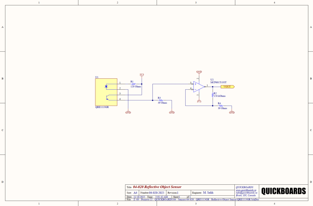
The IR LED within the QRE1113GR (U1) is driven by the 3.3V supply rail through resistor R1. Resistor R1 is set to 120 Ohms to define the forward current ($I_f$). Assuming a typical forward voltage ($V_f$) of 1.2 Volts for the IR LED, the current is calculated at 17.5 mA. This selection balances high optical output with power efficiency and long-term reliability, remaining well below the 50 mA absolute maximum rating.
Signal Conditioning and High-Gain Amplification
The detector stage consists of a load resistor R3 (39 Ohms) and a non-inverting operational amplifier stage (U2, the MCP601). R3 serves as a current-to-voltage converter for the phototransistor. A resistance of 39 Ohms is exceptionally low for this role, prioritizing a very fast response time and preventing the phototransistor from saturating under high-reflectivity conditions.
To compensate for the low voltage generated across R3, the MCP601 is configured as a non-inverting amplifier with a massive gain. The gain is defined by R2 (158 kOhms) and R4 (39 Ohms). The gain factor is calculated as $1 + (158,000 / 39)$, resulting in a theoretical gain of approximately 4052. This design choice allows the system to detect extremely faint reflections from dark or distant objects while maintaining a high signal-to-noise ratio at the VOUT node.
Component Selection
Resistors R2 and R4 are critical for gain stability. Using 1% tolerance resistors ensures that the high-gain stage remains consistent across production units. The choice of 158 kOhms and 39 Ohms specifically leverages precision E96 values to hit the target gain precisely. The MCP601 op-amp is selected for its rail-to-rail output capability, which is necessary to utilize the full 3.3V dynamic range when the sensor detects a target.
Placement & Trace Logic
Given the extreme gain of the conditioning stage (over 4000x), the physical layout is highly sensitive to electromagnetic interference (EMI). The trace connecting Pin 4 of the QRE1113GR to the non-inverting input of the MCP601 (Pin 3) must be as short as possible to minimize its function as an antenna. A solid ground plane beneath the signal conditioning block is mandatory to provide a stable reference and shield the high-impedance nodes from digital switching noise.
Design Rationale
The decision to utilize a low-value load resistor (39 Ohms) followed by a massive active gain stage, rather than a high-value passive load resistor, is an engineering choice to improve frequency response. High-value resistors at the phototransistor collector interact with the parasitic capacitance of the sensor to create a low-pass filter, which would slow the detection of fast-moving objects. This active approach maintains bandwidth while achieving the necessary sensitivity.
Implementation Insights
A primary engineering consideration for the QRE1113GR is optical shielding. Despite the internal IR filter, strong ambient sunlight or high-frequency fluorescent lighting can induce DC offsets or noise in the phototransistor. For maximum reliability, the sensor should be recessed into a mechanical housing that provides a physical shroud against stray light.
Mechanical alignment is equally critical. The sensor’s output varies exponentially with distance. When integrating this block, ensure that the mechanical tolerances of the assembly maintain the target surface within the 1 mm to 3 mm window. Deviations of even 0.5 mm can significantly impact the analog voltage at VOUT, requiring recalibration in software.
Another factor is the potential for crosstalk if a transparent cover glass is used over the sensor. Infrared light can reflect off the internal surface of the glass and directly enter the detector, creating a permanent high-signal floor. Using separate windows for the emitter and detector or ensuring the glass is in direct contact with the sensor housing is required to eliminate this effect.
Applications
- Paper Edge Detection: Used in printers and scanners to determine the presence, size, and alignment of paper media.
- Line Following for Robotics: Provides high-contrast detection between light-colored floors and dark navigation lines.
- Optical Encoders: Measures rotational speed or linear position by detecting patterns on a moving disk or strip.
- Proximity Switching: Functions as a non-contact button or limit switch in industrial machinery where mechanical wear must be avoided.
Integrating the QRE1113GR into your design
The QRE1113GR modular block provides a pre-validated solution for high-sensitivity reflective sensing. By integrating a low-impedance input stage with a precision high-gain amplifier, this design eliminates the uncertainty of manual gain-staging and helps avoid common issues with slow response times in IR sensing. This production-ready sub-system ensures that your design can accurately resolve reflectivity data while maintaining a robust, low-impedance output for standard microcontroller ADCs.
Skip the tedious research and manual entry. Download the production-ready schematic block for the QRE1113GR directly from the Quickboards Library.