TCIXTMA1 Hydrogen Sensor Reference Schematic Design
The TCIXTMA1 is a high-precision, digital hydrogen sensor specifically engineered for safety-critical applications where the detection of hydrogen gas ($H_2$) is paramount. Utilizing advanced micro-electro-mechanical systems (MEMS) technology combined with a digital signal conditioning backend, this integrated circuit is a staple in the automotive and energy sectors. It is primarily deployed in fuel cell electric vehicles (FCEVs), hydrogen refueling stations, and industrial battery rooms to monitor for leaks that could lead to combustible atmospheres.
Unlock the Quickboards Library
Get instant access to this Altium Schematic and hundreds of other subcircuits. Hardware design, modularized. Schematic + Layout + Firmware. Built to IPC standards for zero re-spins.
Overview of the TCIXTMA1
The sensor provides real-time concentration data over a standardized digital interface, eliminating the calibration complexities and noise sensitivities associated with traditional analog gas sensing elements. Its robust design is optimized for long-term stability and high selectivity, ensuring that the sensor responds specifically to hydrogen without being triggered by other ambient gases or volatile organic compounds (VOCs).
| Technical Specification | Details |
| Supply Voltage (VDD) | 3.3V Nominal |
| Communication Protocol | I2C Digital Interface |
| Hydrogen Range | 0 to 4 percent (Lower Explosive Limit) |
| Operating Current | Low-power optimized |
| Digital Features | Wakeup and Standby modes |
| Operating Temperature | -40 to 85°C |
| Calibration | Factory-calibrated digital output |
| Architecture | Integrated MEMS with ASIC backend |
Pin Configuration and Function Mapping
The TCIXTMA1 is designed with a pinout that facilitates easy integration into modern 3.3V logic systems while maintaining clear separation between power and signal traces.
| Pin Number | Primary Function | Secondary / Peripheral Functions |
| 1 | PP0/SCL | I2C Serial Clock |
| 2 | PP1/SDA/WAKEUP | I2C Serial Data / Wakeup Input |
| 3 | PP2/WAKEUP | External Wakeup Control |
| 4 | GNDD | Digital Ground |
| 5 | PP3 | Programmable General Purpose I/O |
| 10 | VDDREG | Internal Regulator Supply |
| 11 | GNDA | Analog Ground |
| 13 | STDBY | Standby Mode Control |
| 14 | VDD | Main Supply Voltage |
| 6, 7, 8, 9, 12 | NC | No Internal Connection |
Functional Block Analysis & Design Decisions
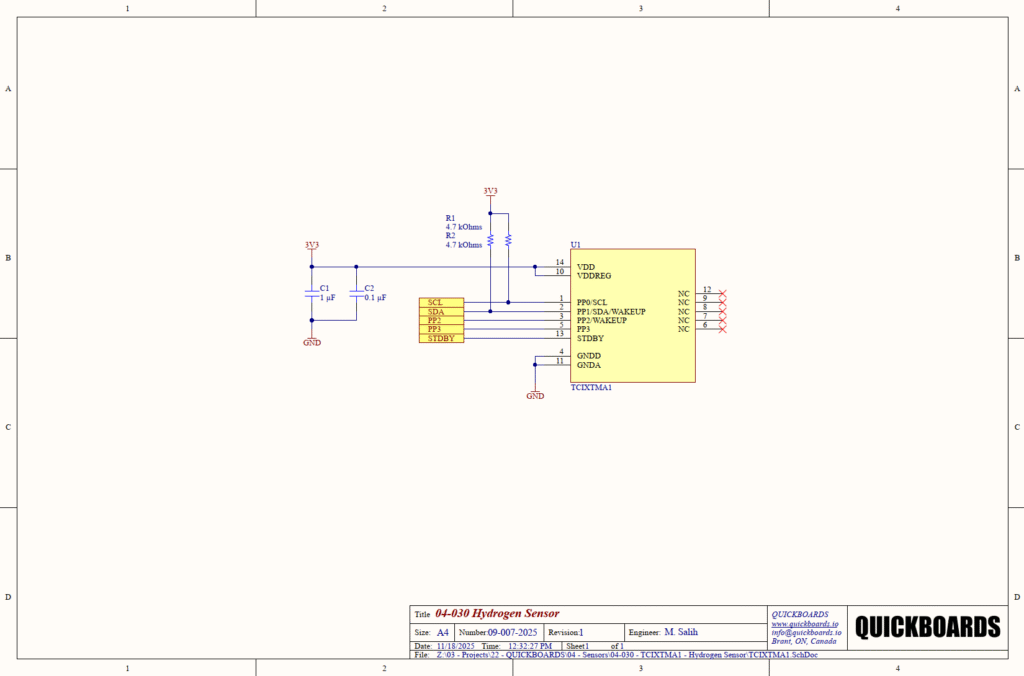
Power Supply and Decoupling Block
The sensor operates on a 3.3V rail (3V3) which powers both the main VDD (Pin 14) and the internal regulator supply VDDREG (Pin 10). To ensure the integrity of the sensitive gas measurements, a dual-capacitor decoupling strategy is implemented using C1 (1uF) and C2 (0.1uF). The 0.1uF ceramic capacitor is a high-frequency bypass component chosen for its low equivalent series inductance (ESL) to filter out fast switching transients from the digital bus. The 1uF capacitor acts as a localized bulk reservoir to stabilize the supply during the sensor’s internal measurement cycles. Both capacitors should be Ceramic X7R types for their superior temperature stability. These components must be placed with maximum proximity to Pin 14 and Pin 10 to minimize trace parasitic effects.
Digital Interface and Bus Biasing
Communication is handled via the I2C interface (SCL and SDA). This reference design utilizes 4.7k ohm pull-up resistors (R1 and R2) connected to the 3.3V rail. A resistance of 4.7k ohms is the industry standard for 400kHz Fast-mode I2C operation; it provides a sufficiently fast rise time to meet timing specifications while minimizing static power consumption when the bus is pulled low by the master or the sensor. These resistors ensure that the I2C lines maintain a stable logic-high state during idle periods, preventing bus floating and potential data corruption.
Control Logic and Grounding
The design exposes the WAKEUP and STDBY pins to allow the host microcontroller to manage the sensor’s power states dynamically. This is critical for battery-powered or energy-efficient automotive systems where the sensor can be kept in a low-power standby mode until a measurement is required. A significant design detail is the separation of GNDD (Digital Ground) and GNDA (Analog Ground) at the IC level. While tied together at the system ground plane in this schematic, senior engineers should note that the physical layout should ideally connect these at a single “star” point to prevent digital switching noise from coupling into the sensitive analog sensing frontend.
Implementation Insights
Mechanical placement is as critical as electrical design for hydrogen sensors. Hydrogen is the lightest gas and tends to accumulate at the highest points of an enclosure or room. Designers should ensure that the sensor is mounted in a location where gas flow is likely to concentrate. Avoid placing the sensor in stagnant air pockets or behind mechanical barriers that could delay the detection of a leak.
The transition between Standby and Active modes requires careful timing management in firmware. When the WAKEUP signal is asserted, the sensor undergoes an internal stabilization period. Engineers must account for this startup latency in their safety software to ensure that the initial data readings are within the calibrated accuracy specifications before triggering safety protocols.
Thermal management of the surrounding PCB is also necessary. While the sensor itself is low-power, significant heat sources placed directly beneath or adjacent to the IC can cause localized thermal gradients. This may affect the accuracy of the gas concentration calculations if the internal temperature compensation algorithms are subjected to extreme board-level heat soak.
Applications
- Fuel Cell Electric Vehicles (FCEVs): Monitoring for hydrogen leaks around the fuel stack, storage tanks, and lines to ensure passenger safety.
- Hydrogen Storage Facilities: Providing early warning of leakages in large-scale energy storage and distribution centers.
- Industrial Gas Monitoring: Real-time tracking of hydrogen levels in chemical processing plants and semiconductor manufacturing environments.
- Battery Charging Rooms: Detecting hydrogen buildup during lead-acid battery charging cycles in warehouse or data center environments.
integrating the TCIXTMA1 into your design
The TCIXTMA1 04-030 hydrogen sensor modular block provides a validated, production-ready solution for safety-critical gas detection. By utilizing a pre-tested decoupling and digital interface architecture, this design eliminates the uncertainty associated with high-precision gas sensing and power integrity. This reusable building block ensures that your safety systems are built on a stable hardware foundation, allowing engineering teams to focus on the software-level safety logic and system integration.
Skip the tedious research and manual entry. Download the production-ready schematic block for the TCIXTMA1 directly from the Quickboards Library.